• Die Forumsregeln und Nutzungsbedingungen findet ihr in der Navbar unter Impressum !
    Bitte unbedingt beachten!
    Wie überall im Leben gibt es Spielregeln, so auch hier!
    Die Datenschutzerklärung zum DSGVO findet ihr ebenfalls in der Navbar unter Datenschutzerklärung !
    Hinweis nach DSGVO :
    Es ist hier keinerlei Angabe erforderlich. Alle Angaben in diesem Bereich sind öffentlich sichtbar und werden freiwillig gemacht. Mit einem Eintrag in diesem Bereich erkenne ich dieses an, und bestätige die Datenschutzerklärung zur DSGVO für das Forum gelesen zu haben.

    Danke

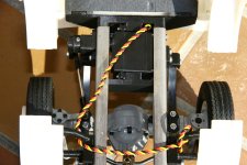
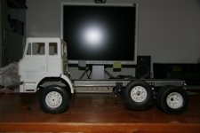
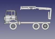
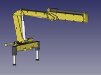
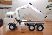
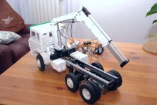
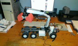
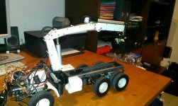
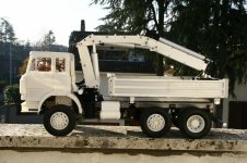
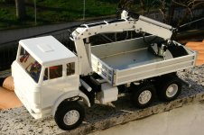
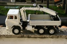
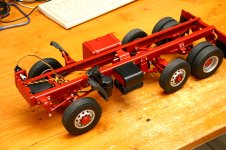
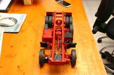
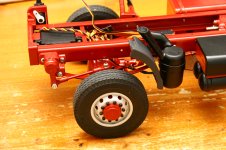
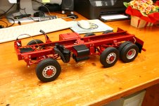
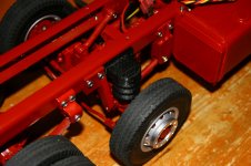
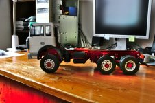
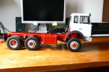
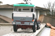
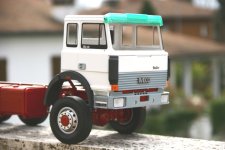
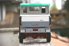
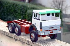
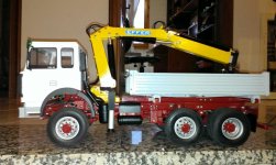
Eigenbau Iveco 250.30 AHW 6x4/4

Luca72

New member
Registriert
02.10.2020
Beiträge
92
main_picture.JPG

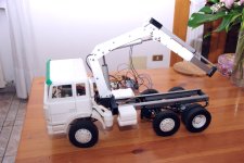
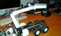
There is a very long story behind the building of this model. It starts at the end of the eighties, when I was quite young. I used to read truck magazines and, in a article regarding an international fair (Geneve?), I saw a very unusual Iveco truck. It was a T-Series with first and third driven axle and idle middle axle. It was for Swiss market. It caught my attention and that picture always remained in my brain. It was there when I started building models in 2013, but the magazine was lost and I did not have enough details in my mind to build a model based on them. Of course I could not remember the name of the model and on the net I could not find any info about a 6x4/4 Iveco truck of those years.

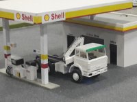
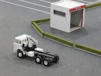
When... all of a sudden (I never give up) I found this pictures on the net. Here it was :hfg
I had the pictures and I had the name of the model. That was all I need to begin building the model. I contacted the editorial staff of the magazine I used to read and I contacted the author of the pictures asking him if he had taken other pictures.

The magazine, at the beginning was not able to recover the articles but, eventually, they found something in their archives and they were so kind to send it to me via mail (free of charge). The author of the pictures, too, was extremely kind and answered my questions. Unfortunately he took no other pictures, but sent me the ones he had in hi-res. Both the magazine docs and the hi-res pictures were fundamental for the building and I could reproduce the truck very realistically.

Now that I had all the info I needed, I had to decide the configuration of the truck. At the time I started building (around 2015) I wanted a construction truck, but I wanted it to be independent, with crane. For a long time I remained unsure of the positioning of the crane: behind the cab (classic) ot at the and of the truck (more appealing but harder to design). Eventually I decided for a classic positioning.

So I started what became my most difficult, longest and expensive truck build. It was only surpassed by the building of the CAT M318, but that is not a truck ;)

All parts I designed for this model can be downloaded at my GitHub: Iveco 250-30 AHW. Just in case somebody were interested in the cab or other part. Everything can be 3Dprinted using PLA or similar filament.

In the next posts I will document the various steps of the (long) building.

Luca
 
Great truck, Luca.:ok:ok:ok


I look forward to your construction report ...

What scale is it?
Is it completely printed (incl. Frame etc...)?


Many greetings

Christian
 
Thanks Christian,
What scale is it?
the truck is 1/14 scale. Same as Tamiya Trucks.

Is it completely printed (incl. Frame etc...)?
No, frame is steel, Axles are from rcbrmin, pistons are self made with ALU, transmission is self made and mostly steel.
Cab, most of the crane, accessories and part of the kipper are 3D printed with PLA. Also the transfer case is 3Dprinted: external is PLA and gears are ALU and 3Dprinted nylon (the central lockable differential).

Regards,
Luca
 
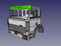
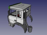
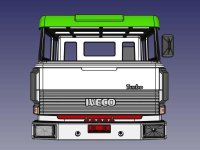
The Cab

Since no Iveco T-range cab was available in 1:14 scale I designed it myself using FreeCAD. There is plenty of documentation about this cab on the Web, so it was quite easy to find pictures, dimensions, etc. I printed some pictures and I scaled everything using tires size as reference (and width that has to be 190mm as Tamiya's).

It took quite a long time to model the cab, because I wanted it to be very similar to real cab.

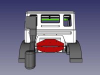
This is the final result, ready to be printed:

cab-full-CAD.jpeg

cab-full-02-CAD.jpeg

cab-full-front-CAD.jpeg

cab-full-rear-CAD.jpeg


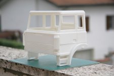
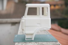
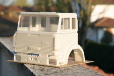
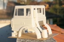
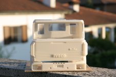
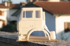
The printing process took many days but at the end the results were even over my best expectations:

IMG_0707.JPG

IMG_0708.JPG

IMG_0719.JPG

IMG_0716.JPG

IMG_0718.JPG

IMG_0717.JPG


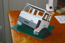
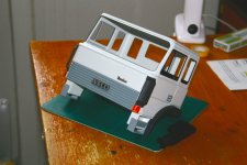
Once the cab printing was over I cured the surface with Tamiya putty, spray filler and I sanded everything. At the end I painted the cab to resemble the one of the model I wanted to reproduce:

IMG_3595.jpg


I did not have violet transparent filament, so I had to print the sunshield using T-Glase green filament.

The next step was the Frame. Many info were missing, but I assumed the 250-30 AHW had to be quite similar to 180-34 AHW, 190-30 AHW, etc. which are very well documented on the Web. One missing part was the central axle. Was it liftable? How was the steering actuated? If nobody could give me the missing Info I had to design something from scratch.

Luca
 
Frame

Once the cab was ready I waited for the axles from Rcbrmin to arrive. In the meantime I designed frame cross members, cab attachment and the transfer case.


The transfer case

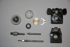
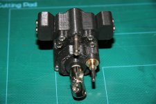
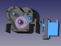
I wanted transmission to me more realistic possible. I Designed transfer case to resemble the one mounted on 180-34 AHW. I designed a lockable differential and a lock/unlock system, driven by micro-servo.
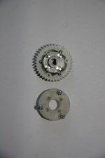
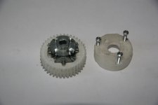
The case was 3Dprinted with strong PLA and the diff case was 3Dprinted with Taulmann Bridge Nylon:

IMG_0795.JPG

IMG_0796.jpg

IMG_0797.JPG

Inner gears and Rods were from Tamiya standard diffs. On one planetary gear I drilled four holes to couple with the sliding lock. Lock has two keys so there are four different lockable positions per rotation. This makes more smooth the insertion of the lock.


Here can be seen the mounted transfer case with input shaft, the two output shaft and the locking remote command bar.

IMG_0801.JPG

IMG_0802.JPG

IMG_0803.JPG


Axles

Eventually the axles arrived and they were quite heavy. Both are remote lockable (I will never know if real truck had frol locker, but I took it for granted :hfg ).

IMG_0775.JPG

IMG_0774.JPG


Wheels
The pictures I found on the Web showed trilex rims, but the model I remembered from the magazine had standard alloy rims. I decided for the latest, but recently I designed trilex wheel and I replaced the first ones.

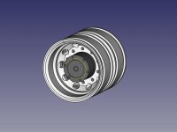
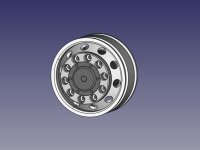
This is the first modeling:

rear_wheel_CAD.jpeg

front_wheel_CAD.jpeg


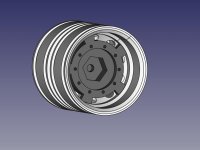
Front and rear rims has HEX for transmission and central rims had hole for bearings:

rear_wheel_hex_CAD.jpeg

Frame assembled

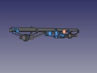
This is the CAD project for the frame. Blue part are PLA, dark parts are steel/brass and orange parts are 3Dprinted rubber

frame_CAD.jpeg

Based on pictures I designed the central axle to be liftable with air baloons. At the time I designed the project I still did not know anything about central axle. I simply tried to reproduce the pictures I found.

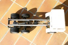
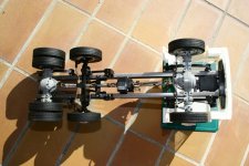
Here is the real frame assembled for initial size tests:

IMG_2922.JPG

IMG_2915.JPG


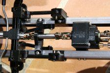
Detail of the transfer case assembled and mounted:

IMG_2916.JPG


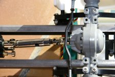
Details of the front axle:

IMG_2918.JPG

IMG_2924.JPG


Here a picture with central axle lifted:

IMG_0788.JPG


This is all for the frame, next step will be the the crane and it will be a VERY difficult step.

Luca
 
Gearbox

Describing the transmission I forgot to mention the gearbox. I wanted to use standard Tamiya 3-speed gearbox, but it was too long for this model. It went way after the cab and it could not be monted in the lower posizion (as in standard Tamiya trucks) because of the front driven axle. So I decided to design a new compact 2-speed (more than enough for a construction machine) gearbox which uses Tamiya gearbox gears (higher gear and lower gear).

Here is the CAD final model (unfortunately I have no real pictures of the gearbox):

gearbox_CAD.jpeg


Here is the top view: considerably shorter than Tamiya own one:

gearbox_topview_CAD.jpeg


The fork was Tamiya's but I had to re-design the selector to have different shapes on the two faces and it was made from ALU using a CNC machine. Probably it would have worked the same if I had used 3Dprinted Nylon.

Gearbox worked flawlessly since the first assembly. Never a problem from this side.


Luca
 
Hey Luca. This is a very good building report. I’m fascinated by your building skills. The 3D printed parts look very true to size. The cabin looks really realistic. My greatest respect, for this project. I will keep my first row seat for the ongoing building report. Keep going! :ok :winker
 
Great work Luca,

and well documented. At the moment I make my first try with FreeCad. At the end I will built it in the traditional way without 3D print.
 
The crane: part one

The first decision was the position of the crane, behind the cab or at the end of the chassis? :frage

crane-cab-side.jpg

crane-end-side.jpg

I really wanted to use the latter solution, but it was really harder to realize, mainly because of the higher rotation angle which needs longer and more articulated (fake) tubing.

At the end I choose classic position behind the cabin and I started design the crane this way.

Making the crane hydraulic was the perfect solution, but... There was not enough space for oil reserve, pump and distributor, since I needed 10 channels. And the cost would have been enormous. So I decided for self built electrical cylinders.
Wiring thus became the "fake"hydraulic tubing. I decided for a clamshell bucket to make the truck completely independent. I decided to reproduce a small Effer crane (like 35/3s) with only one telescopic extension.
Stabilizers were extendable on both sides.

Everything had to be 3Dprintable exception made for the cylinders.

This is the complete crane without the bucket:

crane-main-CAD.jpeg


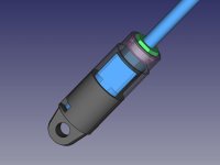
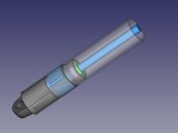
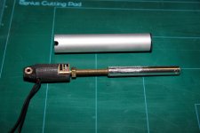
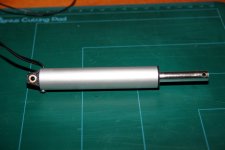
Cylinders were realized using 16x1mm ALU tubes, with a Pololu micro motor (HP) inside the tube. Since Polulo motor external diameter was 15mm I had to drill one side of the tubing, leaving just 0.5mm of material.
The attachment of the cylinder and the motor holder were 3Dprinted (I tried various filaments and I found PetG to be the most reliable one). The inner screw initially was M5 but later I used trapezoid screws (though I did not find any great improvement :hm?). The screw is enlarged (using a M5 NUT) at the base in order to push on a bearing instead than on the motor. I user 1:250 ratio for the main cylinder, 1:100 ratio for the second cylinder and 1:50 ratio for the extender (which uses M3 screw).

crane-cylinder-motor-CAD.jpeg

crane-cylinder-CAD.jpeg


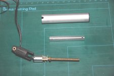
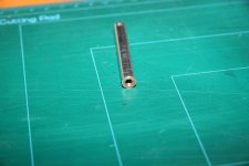
Here is the cylinder disassembled (this pictures miss the bearing. I added it later, after field tests):

IMG_0840.JPG

IMG_0841.JPG

IMG_0844.JPG


And here is finally assembled:

IMG_0845.JPG


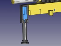
The stabilizers opened using two Pololu motors inside the base of the crane (ratio 1:50) and the foot lowered using Pololu motors inside the cylinder head. To avoid foot rotation I set two tubes, 12x1mm and 10x1mm one inside the other one and I cut a vertical slide in the inner one (2mm wide). Then I fixed a smal 2mm pin on the inner cylinder (diam. 8mm) so that it can on go up and down without turning.

crane-stabilizers-motors-CAD.jpeg

crane-stabilizers-feet-motors-CAD.jpeg


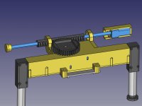
Rotation was initially ,made 3Dprinting a rack gear and moving it horizontally using a Pololu motor (1:50 ratio) and a M3 screw. But rotation angle was very limited (less than 180 degrees) due to the size of the pinion gear (it could not be made smaller than the crane main arm base). At the end I decided for a simpler worm screw that rotates the same pinion gear. Easier and it allowed me to obtain almost 360 degrees of rotation.


This CAD pictures shows the older solution with the rack screw

crane-rotation-motor-CAD.jpeg


Next step will be the clamshell bucket.

Luca
 
Great work, Luca :like
 
The crane: part two (clamshell bucket)

Since I wanted to be able to load my dump truck by myself (when I built it I did not have my new CAT M318) I decided to create a clamshell bucket for my crane. Of course I wanted it to rotate, so to be able to move and position objects like tubes, etc.

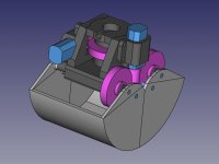
This was the design:

bucket-CAD.jpeg


I bought a couple of worm gears reductions and I used one for rotation (coupled with a Pololu 1:100 ratio gearmotor) and One for opening (same gearmotor).
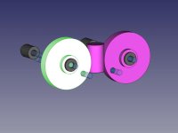
I coupled the motor with one worm gear and each shell with a gear. Then I drilled the gears (they were made of nylon, very easy drilling) and fixed them on the shell with two 3mm bars each.
It worked perfectly and aesthetic was not terrible (at least to my eyes :heilig)

bucket-opening-gears-CAD.jpeg

Everything was 3D printed with PLA and covered with epoxide resin. It turned out extremely strong, I used it to lift big stones up to 400/500 grams and I never broke a tooth or a shell. The only problems I had were with the thin wiring that was quite exposed and sometimes broke near the soldering. I had to resolder quite a number of times...

Luca
 
The crane: part three (electronics)

The crane has 10 motors. This lead to TWO big problems:
a) using a speed regulator (like CTI Thor, for example) for each motor is VERY expensive
b) even though I use a 16 channel radio (FrSky Taranis) I had not enough channels for the whole truck

I found a solution that was good for both points: I built myself a 10 motor controller board that used SBus. This way I had to create Outputs just for the four sticks movements (I could not re use steering and throttle because SBus uses the output channel and it includes centering, trimming etc) and a couple of switches (used to multiplex the sticks via software). This way I spared four channel and I was able to keep one radio program (other solution would have been to use the crane as a stand-alone model with its own receiver).

OK, now I had to design the board and make it work. Luckily I am an Electronic and SW designer in the Automation field, so I only had to apply my everyday work :)

I decided to use an Arduino board coupled with dual H-Bridge ICs (initially I used TI L293D but later I moved to SN754410 which gives a little more power). To read from the SBus I used Arduino SBUS library, and I inverted the SBUS signal (using a transistor) as indicated in the Readme of the library.

Every single motor needed a lot of wiring:
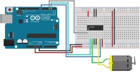
Arduino_L293D.jpg

I had to use an Arduino Mega2560 and I used almost all available pins

Here is the SW I put inside the Arduino:


Code:
#include <SBUS.h>
#include <L293D.h>


#define MOTOR_MAIN_ARM_ENABLE_PIN   		2
#define MOTOR_SECONDARY_ARM_ENABLE_PIN   	3
#define MOTOR_ROTATION_ENABLE_PIN   		4
#define MOTOR_EXTENDER_ENABLE_PIN   		5
#define MOTOR_BUCKET_ENABLE_PIN   		6
#define MOTOR_BUCKET_ROTATION_ENABLE_PIN 	7
#define MOTOR_STABILIZER_LH_EXT_ENABLE_PIN 	8
#define MOTOR_STABILIZER_LH_ELEV_ENABLE_PIN 	12
#define MOTOR_STABILIZER_RH_EXT_ENABLE_PIN 	13
#define MOTOR_STABILIZER_RH_ELEV_ENABLE_PIN 	11

#define MOTOR_MAIN_ARM_A_PIN        		44
#define MOTOR_MAIN_ARM_B_PIN        		45
#define MOTOR_SECONDARY_ARM_A_PIN        	34
#define MOTOR_SECONDARY_ARM_B_PIN        	35
#define MOTOR_ROTATION_A_PIN        		42
#define MOTOR_ROTATION_B_PIN        		43
#define MOTOR_EXTENDER_A_PIN        		46
#define MOTOR_EXTENDER_B_PIN        		47
#define MOTOR_BUCKET_A_PIN        		32
#define MOTOR_BUCKET_B_PIN        		33
#define MOTOR_BUCKET_ROTATION_A_PIN             36
#define MOTOR_BUCKET_ROTATION_B_PIN        	37
#define MOTOR_STABILIZER_LH_EXT_A_PIN 	        40
#define MOTOR_STABILIZER_LH_EXT_B_PIN 	        41
#define MOTOR_STABILIZER_LH_ELEV_A_PIN 	        48
#define MOTOR_STABILIZER_LH_ELEV_B_PIN 	        49
#define MOTOR_STABILIZER_RH_EXT_A_PIN 	        30
#define MOTOR_STABILIZER_RH_EXT_B_PIN 	        31
#define MOTOR_STABILIZER_RH_ELEV_A_PIN 	        38
#define MOTOR_STABILIZER_RH_ELEV_B_PIN 	        39


SBUS sbus(Serial3);
L293D motorMainArm(MOTOR_MAIN_ARM_ENABLE_PIN, MOTOR_MAIN_ARM_A_PIN, MOTOR_MAIN_ARM_B_PIN);
L293D motorSecondaryArm(MOTOR_SECONDARY_ARM_ENABLE_PIN, MOTOR_SECONDARY_ARM_A_PIN, MOTOR_SECONDARY_ARM_B_PIN);
L293D motorBucket(MOTOR_BUCKET_ENABLE_PIN, MOTOR_BUCKET_A_PIN, MOTOR_BUCKET_B_PIN);
L293D motorRotation(MOTOR_ROTATION_ENABLE_PIN, MOTOR_ROTATION_A_PIN, MOTOR_ROTATION_B_PIN);
L293D motorExtender(MOTOR_EXTENDER_ENABLE_PIN, MOTOR_EXTENDER_A_PIN, MOTOR_EXTENDER_B_PIN);
L293D motorBucketRotation(MOTOR_BUCKET_ROTATION_ENABLE_P  IN, MOTOR_BUCKET_ROTATION_A_PIN, MOTOR_BUCKET_ROTATION_B_PIN);
L293D motorStabilizerLeftExt(MOTOR_STABILIZER_LH_EXT_ENA  BLE_PIN, MOTOR_STABILIZER_LH_EXT_A_PIN, MOTOR_STABILIZER_LH_EXT_B_PIN);
L293D motorStabilizerLeftElev(MOTOR_STABILIZER_LH_ELEV_E  NABLE_PIN, MOTOR_STABILIZER_LH_ELEV_A_PIN, MOTOR_STABILIZER_LH_ELEV_B_PIN);
L293D motorStabilizerRightExt(MOTOR_STABILIZER_RH_EXT_EN  ABLE_PIN, MOTOR_STABILIZER_RH_EXT_A_PIN, MOTOR_STABILIZER_RH_EXT_B_PIN);
L293D motorStabilizerRightElev(MOTOR_STABILIZER_RH_ELEV_  ENABLE_PIN, MOTOR_STABILIZER_RH_ELEV_A_PIN, MOTOR_STABILIZER_RH_ELEV_B_PIN);


int channel09_ModeSel = 0;
int channel11_Tip_BkRot = 0;
int channel12_Ext = 0;
int channel13_LhHr = 0;
int channel14_LhVr = 0;
int channel15_RhVr = 0;
int channel16_RhHr = 0;


static long nextPrintStatusTime = 0;
#define PRINT_STATUS_DELAY  500


void setup()
{
  sbus.begin();

  //TCCR3B = (TCCR3B & 0xF8) | 0x02 ; //set frequency of pins 2, 3, 5
  
  Serial.begin(115200);
  Serial.println("RC Iveco 250 MFU");
}

// this is timer2, which triggers ever 1ms and processes the incoming SBUS datastream
ISR(TIMER2_COMPA_vect)
{
  sbus.process();
}


void loop()
{
  long currentTime = millis();

  channel09_ModeSel = sbus.getNormalizedChannel(9);

  channel11_Tip_BkRot = sbus.getNormalizedChannel(11);
  channel12_Ext = sbus.getNormalizedChannel(12);
  channel13_LhHr = sbus.getNormalizedChannel(13);
  channel14_LhVr = sbus.getNormalizedChannel(14);
  channel15_RhVr = sbus.getNormalizedChannel(15);
  channel16_RhHr = sbus.getNormalizedChannel(16);

  if (channel09_ModeSel > 50)
  {
    motorMainArm.set((channel14_LhVr / 100.0) * 1.2);
    motorSecondaryArm.set((channel15_RhVr / 100.0) * 1.2);
    motorRotation.set((channel13_LhHr / 100.0) * 1.2);
    motorBucket.set((channel16_RhHr / 100.0) * 1.2);
    motorExtender.set((channel12_Ext / 100.0) * 1.2);
    motorBucketRotation.set((channel11_Tip_BkRot / 100.0) * 1.2);
    motorStabilizerLeftExt.set(0);
    motorStabilizerLeftElev.set(0);
    motorStabilizerRightExt.set(0);
    motorStabilizerRightElev.set(0);
  }
  else if (channel09_ModeSel == 0)
  {
    motorMainArm.set(0);
    motorSecondaryArm.set(0);
    motorRotation.set(0);
    motorBucket.set(0);
    motorExtender.set(0);
    motorBucketRotation.set(0);
    motorStabilizerLeftExt.set(-(channel13_LhHr / 100.0) * 1.2);
    if(motorStabilizerLeftExt.get() == 0)
      motorStabilizerLeftElev.set((channel14_LhVr / 100.0) * 1.2);
    else
      motorStabilizerLeftElev.set(0);
    motorStabilizerRightExt.set((channel16_RhHr / 100.0) * 1.2);
    if(motorStabilizerRightExt.get() == 0)
      motorStabilizerRightElev.set((channel15_RhVr / 100.0) * 1.2);
    else
      motorStabilizerRightElev.set(0);
  }  
  else if (channel09_ModeSel < -50)
  {
    motorMainArm.set(0);
    motorSecondaryArm.set(0);
    motorRotation.set(0);
    motorBucket.set(0);
    motorExtender.set(0);
    motorBucketRotation.set(0);
    motorStabilizerLeftExt.set(0);
    motorStabilizerLeftElev.set(0);
    motorStabilizerRightExt.set(0);
    motorStabilizerRightElev.set(0);
  }  
/*  
  if(currentTime > nextPrintStatusTime)
  {
    printStatus();
    nextPrintStatusTime = currentTime + PRINT_STATUS_DELAY;
  }
*/  
}


void printStatus()
{
  Serial.print("CH9_ModeSel: "); Serial.println(channel09_ModeSel);
  Serial.print("CH11_Tip_BkRot: "); Serial.println(channel11_Tip_BkRot);
  Serial.print("CH12_Ext: "); Serial.println(channel12_Ext);  
  Serial.print("CH13_LhHr: "); Serial.println(channel13_LhHr);    
  Serial.print("CH14_LhVr: "); Serial.println(channel14_LhVr);
  Serial.print("CH14 TRUE: "); Serial.println(sbus.getChannel(14));
  Serial.print("CH15_RhVr: "); Serial.println(channel15_RhVr);    
  Serial.print("CH16_RhHr: "); Serial.println(channel16_RhHr);      
  Serial.print("Lost Frames: "); Serial.println(sbus.getLostFrames());    
}

Here is one of the first tests with wiring still on breadboard (crane was fixed to the table with EXTRA STRONG double stick tape):

Um diese Inhalte anzuzeigen, benötigen wir die Zustimmung zum Setzen von Drittanbieter-Cookies.
Für weitere Informationen siehe die Seite Verwendung von Cookies.


The hardest part was the wiring. Initially I planned to use a Arduino Mega 2560 PRO Mini which has a form factor really small compared to standard "Mega". I hoped to put the board inside a fake oil tank beside the crane main arm. But wiring on pre-drilled board turned out a nightmare. All pins of the "Mega 2560 PRO Mini " where on twin rows and soldering so many wires brung to a number of short circuits. After a while I had to give up. It was a no-go... So I had to turn to standard "Mega" and board had to be moved inside the cab :(

Wiring was all but easy even with the bigger board. I used four ICs as double H-bridge, with two motors attached, and two ICs as double power H-bridge (using two H-b joined together to double the output power) for the main cylinders. I spent a huge amount of time checking every single connection and fixing many short circuits. But at the end I had it working.

Here is the board inside the cab:
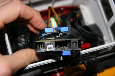
IMG_4654.JPG

IMG_4653.JPG


To end the "electronic chapter" I have to describe the motors choice. initially I bough cheap N20 gearmotors, but it turned out the were HUGELY under powered for my needs. I had to turn to original POLOLU micro motors in HPCB version. Sadly they are really expensive, something like 15 EURO each. But they are 6V rated, so I hoped to use a single 2S battery for the whole model. Also this turned out wrong, partly because of the H-bridge dropout and partly because main cylinder needed very high strength. So I had to use a 3s LiPo just for the crane and give 12V to the motors (they are rated 3-9V and considering the IC dropout I did not go too much out of specs). This made them very short living especially the main cylinder one. Initially when I still used 1:100 / 1:150 ratio I had to replace it every time I used the crane for long. Then I moved to 1:250 ratio plus trapezoid screw and things got a little better.


This is the actual configuration of the motors

First cylinder: POLOLU 250:1 Micro Metal Gearmotor HPCB 6V
Second cylinder: POLOLU 100:1 Micro Metal Gearmotor HPCB 6V
Extender: POLOLU 50:1 Micro Metal Gearmotor HP 6V
Bucket (both motors): POLOLU 100:1 Micro Metal Gearmotor HP 6V
Stabilizers (all four motors): POLOLU 50:1 Micro Metal Gearmotor HP 6V
Turntable: POLOLU 100:1 Micro Metal Gearmotor HP 6V


Luca
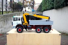
 
The crane: part four (on the truck)

With electronics working and almost all the parts printed and assembled (stabilizers came later), it was time to go on the truck!!!

Here is the very first assembly, testing the motors and the strength. Here I am still using the breadboard, the board had still to come.

IMG_3009.jpg

IMG_3012.jpg

IMG_3014.jpg

I tried to lift a bottle of water and in that initial configuration (main piston had 1:100 gearmotor) max lifting allowed was 500 g (enough for the use of clamshell crane, but not very good :( )


Then I installed the clamshell bucket. initially I designed a HUGE bucket , but it seemed way too big for the truck (sorry for the blurry picture :( it was the only one with the big orange bucket):

IMG-20151219-WA0001.jpg


So I redesigned it smaller (but I still blurred the pictures... shame on me since I am an hobbyist photographer...):

IMG-20151221-WA0001.jpg

IMG-20151221-WA0003.jpg


This is all for the crane (for now, I will complete it later)

Luca
 
First time in public (still mostly unfinished): Bologna Model Game Expo 2015

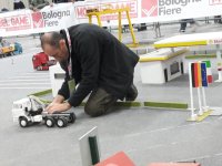
At Bologna Model Game Expo 2015 (I was one of the organizers of the truck area) I decided to bring the Iveco 250 with me even if it was barely running. Of course I left the breadboard with the electronic at home, so the crane was just aesthetic, folded behind the cab. It stayed in the parking for the whole weekend, but I gave it a small run just before closing on Sunday.

This pictures were taken by a friend of mine who came visiting the Expo

20151122_171038.jpg

20151122_170147.jpg


Since I was not the one taking picture, I can appear in them :)

20151122_170236.jpg

20151122_171142.jpg


Here is a video of the small run:

Um diese Inhalte anzuzeigen, benötigen wir die Zustimmung zum Setzen von Drittanbieter-Cookies.
Für weitere Informationen siehe die Seite Verwendung von Cookies.


Next fair was due in a couple of months (Modena Mo-Del, January 2016) and for that date I wanted (at all costs) the truck to be complete and running.
The kipper was to be completely designed and the crane electronic board was absolutely necessary.

A lot of work still to be done.

Luca
 
Ciao Luca,
Another interesting model.
Thanks for the detailed explanation and for the data released for download. Thanks to FreeCAD original data, it is even easier to adapt it. So one can see how you proceeded and learn something.
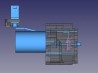
Yesterday I couldn't resist and reprinted the tank tonight.

And now we even have Luca in colour - in the video.
 
The kipper

The kipper was the last missing part and it was time to build it. I wanted a trilateral kipper with low sides. I wanted it independent from the truck so I built it with its own frame. You can easily remove it from the main frame.
I used a classic RB35 motor with 8mm spindle. I decided to print the lifting arm with PLA. I was really unconvinced by its strength, but after five years and many unloading it is still there :)

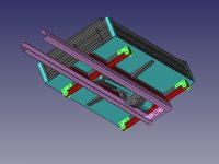
This is the design of the whole kipper, dark parts are PLA, blue parts are metal (mainly ALU) and red parts is the metal frames. The truck frame is highlighted in pink color.

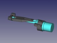
In this first picture there is the unloading mech. It can lift the kipper to the rear and to the sides too, thanks to the HEXthat can turn the arm to both sides. In the head of the arm there is a classic steering uniball.
In the lower position the motor is stopped by an endstop, and in the higher position I removed part of the thread with the lathe so that the HEX stops running and starts jumping, helping the unload of the dirt.

kipper-spindle-motor_CAD.jpeg


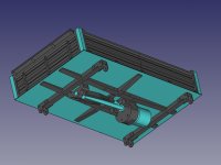
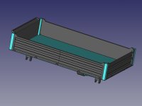
Here is the kipper on the upper side and on the lower side with the motor and the lifting mech attached. As can be seen the spindle is inclined some degrees to allow more leverage during initial part of the lifting. The base of the kipper is a thin (0.8mm) layer of ALU. The sides and rear panel can open and are kept in position by some little (3mm diam) magnets glued inside the walls

kipper-bottom_CAD.jpeg

kipper-top_CAD.jpeg


Here is the complete kipper with part of the truck frame.

kipper-bottom_frame_CAD.jpeg


I wanted to use three small servos to select from the radio the unloading side, but I was really short of channels on the receiver, I only had one left for unloading. So side selection (for now) is made manually using rods to lock two of the four joints (highlighted in green in the last picture) of the frame.


Initial project had ALU sides with 3Dprinted pattern on the external. But eventually I went for full 3D printed sides (lighter).

IMG_3305.jpg

IMG_3300.jpg

IMG_3298.jpg


Even not 100% complete (axle lifting was still missing, stabilizers were not ready and, of course, it needs some paint :hfg ) now the truck is ready for its second fair: Mo-del Expo January 2016 in Modena.
In the meantime I finished wiring and testing the crane electronics :)

Luca
 
Model (almost) complete: last test in my garden and Modena Mo-Del Expo January 2016
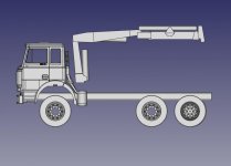
Just in time for the end of 2015 I got the model (mostly) complete: only the second axle lifting was missing (and of course the painting) but it worked more or less as expected.
So it was time for a final test before Mo-Del Expo in Modena, due for mid January 2016:

Um diese Inhalte anzuzeigen, benötigen wir die Zustimmung zum Setzen von Drittanbieter-Cookies.
Für weitere Informationen siehe die Seite Verwendung von Cookies.


I spent my free time of the next two weeks making preparations with my club for the next Expo. Sadly Mo-Del does not allow for earth or sand so we just had some cat's litter :(

Here are some pictures of my model at the Expo:

Iveco250_MO2016_001.jpg


Here it is finally doing something "useful" :hfg

Iveco250_MO2016_002.jpg

Iveco250_MO2016_003.jpg


Ok, it was time for painting. No more excuses :sauer

Luca72
 
Painting

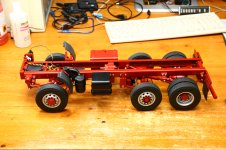
This was my first model with red frame. I have to admit I love trucks with this brownish red colored frames.

At the beginning I wanted the real paint, which is not a RAL color, but at the end I opted for RAL 3011, easier to find a a little more brilliant. I liked the final result. For the cab I chose WHITE as the pictured found on the web. I made the crane yellow like most Effer cranes and I choose an anonymous GRAY for the kipper.

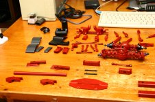
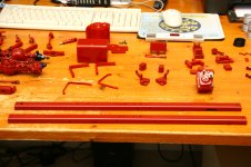
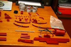
Painting took a VERY long tome since there were so many little pieces to cure (3D print needs a lot of filler) and paint. The cab, especially, needed a lot of curing to hide the Z-lines from 3D printing.
Strange to say, since I am a completely ZERO when it turns to painting, but results were good.

So, one day, I had all pieces on my desk, ready to be assembled. And I really enjoyed that time :cool

IMG_3577.JPG

IMG_3580.JPG

IMG_3582.JPG

IMG_3583.JPG


After a while the brownish red frame was assembled and (at least in my opinion) looked really good :)

IMG_3587.JPG

IMG_3588.JPG

IMG_3590.JPG

IMG_3591.JPG

IMG_3592.JPG

IMG_3616.JPG

IMG_3622.JPG

IMG_3626.JPG


Then it was to time for the cab to be assembled:

IMG_3595.JPG


Then a first look outside:

IMG_3611.JPG

IMG_3606.JPG

IMG_3603.JPG

IMG_3613.JPG


And, finally, crane and kipper were added to the frame (sadly I took no picture of the crane and kipper assembly). I also created the windows using thin transparent plastic found at the local hobbyist store.

IMG-20160331-WA0003.JPG


At this point all major efforts were done. Truck was almost finished and in the following months I brung it with me to many country festivals and fairs.
From 2016 to these days I made some little but significative improvements: axle lifting, improved crane rotation with wormscrew, new trilex rims.
I will describe them in the following posts


Luca
 
Absolutely great idea to mount the steeringservo that way. How did you extend the servogear?

It looks absolutely great. Did you also improve over the years the two screws for the bumperfixing?
 
Hello Luca,
a very nice model. The crane moves very quickly. Did you describe the threaded rods for the cylinders? Normal threaded rods? If so, I must have overlooked it.

Years ago I had read about an excavator conversion. The cylinders (dummies) were turned by servos. There were stone drills in them. So they worked with a very large pitch.
https://www.modelltruck.net/showthread.php?45446-Bruder-Bagger-E-Zylinder-auf-Youtube&styleid=16
https://www.youtube.com/watch?v=43mpUxbapJ4

What do you glue the PLA parts with?

###
Hallo Luca,
ein sehr schönes Modell. Der Kran bewegst sich schön flott. Hattest Du die Gewindestangen für die Zylinder beschrieben? Normale Gewindestangen? Falls ja, muss ich es übersehen haben.

Vor Jahren hatte ich über einen Baggerumbau gelesen. Da wurden die Zylinder (Atrappen) von Servos gedreht. Darin befanden sich Steinbohrer. Sie arbeiteten somit mit einer sehr großen Steigung.

Mit was verklebst Du die PLA Teile?
 
...How did you extend the servogear?
Thanks for pointing it out. I forgot to describe the steering linkage. will do it in the next post!!!!!

...Did you also improve over the years the two screws for the bumperfixing?
No :oops When I started building trucks I preferred functionality vs aesthetics. All my truck have uncovered screws (look at the crane, it is a mess of screws). It is great if something breaks down away from home and you have to dismantle the whole truck to reach the faulty component. But it is absolutely ugly to be seen. Starting from my fourth model (the excavator) I hid all screws with a layer of paintable tape. I have to admit it is nicer.
...The crane moves very quickly. Did you describe the threaded rods for the cylinders? Normal threaded rods? If so, I must have overlooked it.
I described the internal of the cylinders toward the half of this post: The crane: part one. At the beginning (as showed in the pictures) I used standard M5 rods coupled with a bearing to N20 Pololu gearmotor. Then, for the two arm cylinders, I turned to trapezoidal Tr5. With 1mm advance per turn. I hoped to increase by large amount the performance of both cylinders, but it did not :( At the end I barely noticed any difference, except I gained a little speed stepping up from 0.8mm advance/turn of M5 to 1mm advance/turn of Tr5. But the greater couple required, lowered the motors speed. So at the end I would say NO DIFFERENCE. Most of the speed is gained using the motors with 12V (they are rated 3V-9V). The H-bridge I use for driving them has a voltage drop of about 2V (under load) so I am within spec even if at limit. This way the original Pololu HPCB (with carbon brushes) turns at about 40000 RPM (before its little gearbox) .

...What do you glue the PLA parts with?
I have never found anything good for PLA. Superglue sometimes works, but it is always a weak gluing. Epoxy glue works best, but needs loooooong time to cure. Usually If I cannot do otherwise than gluing I use cyanoacrylate then I fix immediately,with its spray activator. It turns out a very brittle gluing but works for some time.


Luca
 
Steering linkage

I forgot to describe it earlier. Unfortunately at the time of building I did not take any picture of it :(

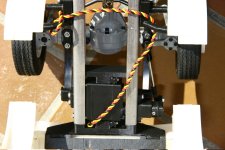
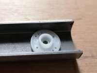
Since the Rcbrmin axles had a realistic steering linkage I had to find a way to set the steering servo in the right position. It turned out that best position was in the middle of the frame, both vertically and horizontally. Problem was how to get the steering servo shaft outside the frame. I had to find a solution to connect it to a 5mm rod.

IMG_2924.JPG


Luckily the round arm that you find in any servo box, came to help: small enough to fit inside the frame.

steering-mount.jpg


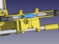
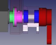
I joined the external arm (3D printed) with a 5mm rod (gray), then I created a BRASS coupler (fuchsia) that fixed in the servo round arm (green) with two M2 screws and to the 5mm shaft with a 3mm grub screw. Two bearings (blue) keeps the shaft straight even under hard steering.

steering-assembly.jpg

I made a big hole in the frame so the BRASS coupler can grab the shaft for a bigger length.


Luca
 

Servonaut
Zurück
Oben Unten