• Die Forumsregeln und Nutzungsbedingungen findet ihr in der Navbar unter Impressum !
    Bitte unbedingt beachten!
    Wie überall im Leben gibt es Spielregeln, so auch hier!
    Die Datenschutzerklärung zum DSGVO findet ihr ebenfalls in der Navbar unter Datenschutzerklärung !
    Hinweis nach DSGVO :
    Es ist hier keinerlei Angabe erforderlich. Alle Angaben in diesem Bereich sind öffentlich sichtbar und werden freiwillig gemacht. Mit einem Eintrag in diesem Bereich erkenne ich dieses an, und bestätige die Datenschutzerklärung zur DSGVO für das Forum gelesen zu haben.

    Danke

Eigenbau Volvo BM LM841

Luca72

New member
Registriert
02.10.2020
Beiträge
92
When I was young I used to go for summer vacations on the Alps in Trentino. There, in a small city called Mezzocorona, there was a wood factory where operated many strange machines. They were like agri tractors but they worked in the opposite way (big wheels ahead) and had arms like wheel loaders with pincers for wood in the place of the bucket. Now I know they were Volvo backloaders, but at the time I watched them with perplexity. They were not good looking, not at all. But they were somehow interesting and always captured my attention when I passed by (usually the first and last day of vacation).

Then I forgot them for some 30 years and, I don't know how or why, they returned into my mind last summer, when I was on vacation in Tuscany. Those days I was lazily designing a wheel loader (CAT 950E) but the process was taking forever. Then, all of a sudden, I decided that my next wheel loader was going to be a Volvo BM LM841. I bought Millimeter paper and I started designing it during the vacation.

This is the machine I am building:
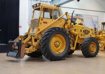
volvo-bm-lm-841.jpg

Photo courtesy of Munktell Museum (Eskilstuna). They kindly gave me permission to publish it.

Data about the machine can be found in the museum machine webpage.

Unlike all the other model that I published, this is still a work in progress so I will not publish the finished model picture in the first page nor the GitHub where to download the parts. They will come during the model development.

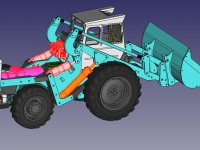
This is the actual progress:
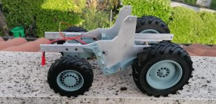
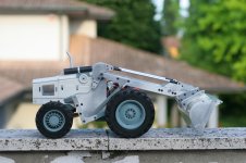
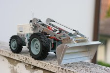
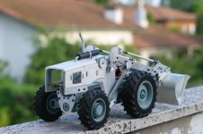
RC-VolvoLM841-2023-05-05.jpg

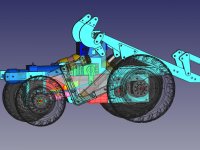
Frame, wheels, axles and transmission are done.


I am proceeding designing the rest of the machine.
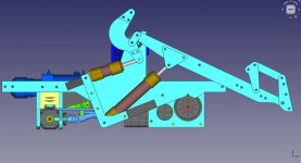
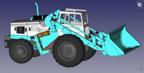
Assembly-CAD-2023-05-05.jpg


In the following posts I will describe in details the work in progress.

Luca72
 
Hello Luca,

great project. In 2016 i make some pictures from a LM840 in france.

https://www.modelltruck.net/showthread.php?57512-Bolinder-Munktell-LM840

I saw this vehicle during a tour with my bicycle, but it has not been found for several years. I have no idea what happened to this vehicle. A replica as a model would also appeal to me.

Best regards,

Matthias
 
Hello Luca

I‘ve seen this machine in Munktellmuseet im Eskilstuna, Sweden. I‘ve only taken ohne picture because this machine Stands between l 218 and a newer Version of Wheel Loader. In the Moment i stand in Front of the loader i think it was mit nice, quiet awfull. But now in distance and with the starting of your project i change my mind.
 
Hello Luca,
great project. In 2016 i make some pictures from a LM840 in france.
https://www.modelltruck.net/showthread.php?57512-Bolinder-Munktell-LM840
...
Thank you. You made some interesting pictures, they will be useful for my project, for some details of the rear.

...
A replica as a model would also appeal to me.
...
I am going to publish all the parts files plus the assembly file, once the project is finished. You could use them (all or some of them) to build a replica.

Luca
 
Design on paper

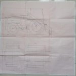
When I decided I absolutely had to build and RC replica of Volvo LM841 I was traveling in the beautiful Tuscany hills (and still I do not understand what triggered me) and Autumn 2022 had just begun. Once I arrived at my final destination (Grosseto) and settled in the apartment, I bought some millimeter paper and a ruler. There, in the spare time (it is strange to mention "spare time" when you are on vacation :) ), I scaled the machine using original Volvo data sheets and my girlfriend tablet. Luckily LM841 data sheets are quite easy to find on the internet.

This is all I got in two weeks:
volvo-lm841-design.jpg

To make a 4x4 machine with different wheels size I had to design the tires to be in a finite proportion between them So I decided for 124mm for front wheels diameter and 92mm for rear wheels diameter. This more or less respect 1:13.2 scale and gives me the possibility to divide both diameters by 4 and obtain 31:23. I used this number to design the tooth of gears that divided front and rear transmission. It worked like a charm :hfg

Once I finished scaling the whole machine on paper I knew there was a good probability that I could build it. Even though space was not much (to implement all the mechanics, servos, battery, oil pump, distributors, etc.) it seemed enough to start the project.

The vacation was almost over and once at home I had to move all the quotes on Freecad.

Luca
 
Wheels

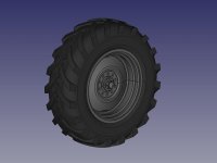
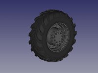
Once I was back at home, I moved the projet from paper to Freecad. With trucks I usually start designing the cab, but with construction machines I start with the wheels.

Luckily I already designed tractor tires, so it was not a first for me. But... once I had the tires designed I did not know how to build them. They were both (front and rear) way bigger then anything I had realized until that moment.

front-wheel-CAD.jpg
Front

rear-wheel-CAD.jpg
Rear

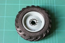
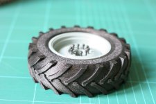
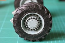
At beginning I decided to use molded silicon rubber (Prochima, for example, makes rubber for models). But then I decided to give (again) a try to printed Rubber. As I did with CAT M318 I printed the tire divided in two halves that I glued using black neoprene glue.

It took 18 hours for every front wheel (9 hours each half) and 10 hours for the smaller rear wheels. But my printer never failed (even though it is a self build old Prusa i3 with wooden frame).

Then I printed both front and rear rims and hubs. The result were beyond my expectation. Both wheels looked very nice.

wheels_and_rims_01.JPG

wheels_and_rims_02.JPG

wheels_and_rims_03.JPG


This gave a big momentum to my project that had been stalling for months.

Luca
 
Axles

With the wheels came the axles.

Axles_Assembly_CAD.jpg

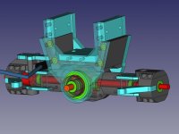
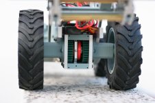
I reused most of CAT M318 steering axle, for the rear axle. But I had to create from scratch the front axle. Real machine has secondary reduction on the axle, just inside the diff box. It is very clear also in the original datasheet. Since the diff is positione behind the axle, the axle lock is between the big gears. I copied the scheme and I took advantage from the reduction and I used it to syncronize the wheels speed (they are different size). I 3D Printed gears with PLA using wheels proportion: 124mm diam and 92mm diam -> 31 teeth on wheel axle and 23 teeth on diff axle. This way both diffs were able tu turn at the same speed.

Front axle design:

Front_Axle_CAD.jpg


Rear axle design:

Rear_Axle_CAD.jpg

Rear axle is oscillating and I created a 5mm ALU structure to keep it in position. Two low profile 23x17x4mm bearings make the oscillation smooth. Top of the structure has been designed to receive the Magom pump.

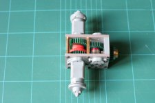
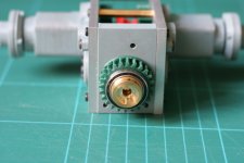
Here are the pictures of the assembled axles:

IMG_4728.JPG

IMG_4729.JPG

IMG_4738.JPG

Luca
 
Hi Luca,

That is a very nice project of an old school loader.:ok:ok:ok

Good luck with the building.

Best Regards, Charlotte.:winker
 
Hi Luca,
That is a very nice project of an old school loader.:ok:ok:ok
Good luck with the building.
Best Regards, Charlotte.:winker

Thank you very much. It started as a quite challenging project, I had no experience with wheel loaders. But now I can say almost all difficulties are over (real project is a little "ahead" compared to this report).

Luca
 
Frame (1st part)

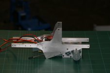
Once both axles were ready I needed a frame to test that everything could fit in place. At the beginning I thought about a classic truck frame with two "C" shaped bars, one each side.
But, after analyzing many pictures I found that real machine has a more complex frame which extend to arm support and pistons support. This way I could make a more robust frame.

Frame_Assembly_CAD.jpg

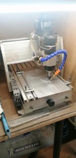
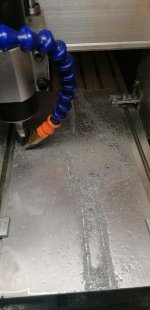
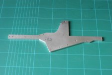
But I had to cut a 300x120mm ALU shape out of a5mm ALU plate. My small CNC router had never managed such a big job, but it went really smoothly with both sides cut in less than five hour.

IMG_20230423_173300.jpg IMG_20230423_173416.jpg


Result was pretty neat

IMG_4727.JPG


Here with front axle attached:

IMG_4760.jpg

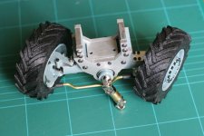
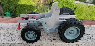
And here with both axles and wheels:

IMG_20230505_183550.jpg


With a metal frame that was able to keep in position almost all parts of the machine, the rest of the design was really easier. And it turned out REALLY rigid.


Luca
 
Wow, looks very good.
Thanks for this report. :klack
br
 
Gearbox

Gearbox_Assembly_CAD.jpg


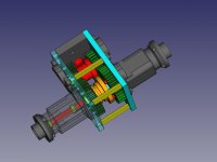
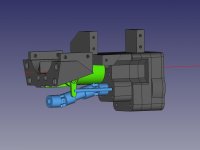
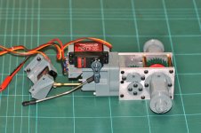
Real machine has 2 speed forward + 2 speed backward and a reductor that makes 4+4 speed total. Reductor in low range allows the engage of the rear axle. I hoped to be able to design at least the reductor in order to have 2+2 speed. But the space was not enough. I will try tu simulate the reductor elettrically.

In the little space, below steering servo, battery, pump, I had to find space for the gearmotor and the disengage mech for the rear axle (that was a priority). After trying many different position I found the way to squeaze everything inside.

Gearbox_01_CAD.jpg


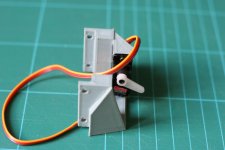
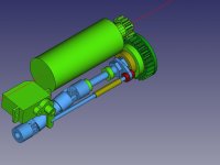
For the disengage I reused a shaft from Tamiya gearbox that has splines and a HEX which engages on them (it is originally used for the gears). With the CNC router I modified it to engage in a custom ring using a brass fork.

Disengaged and engaged:

Gearbox_03_CAD.jpg Gearbox_04_CAD.jpg


Here a view of the mounted parts:

IMG_4731.JPG


I manually modified a 5mm brass rod to fit in the servo lever:

IMG_4733.JPG


Engage (micro) servo (EMAX ES08MAII) found its place between gearbox and rear axle.

IMG_4730.JPG


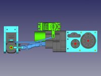
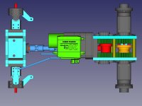
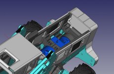
Here is the inner mech as designed on FreeCAD:

Gearbox_02_CAD.jpg

Gearmotor is an High Current (16A stall current) GM25-370K gearmotor with 250 RPM speed. It needs some current so I will use a CTI Thor 14 ESC as I did with my CAT M318 excavator.


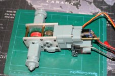
And here are a couple of pictures of the finished gearbox, mounted attached to the front axle ( a couple of screws on the rear fix it at the frame ):


IMG_4773.jpg

IMG_4754.jpg

The gearbox also gives a mount to the steering servo.


Luca
 
Steering

Steering_Assembly_CAD.jpg

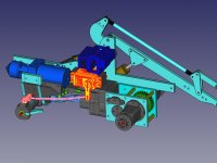
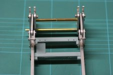
Steering servo was fixed just above gearbox (and gearbox itself provided the attach structure). I had to work a little with FreeCAD to find a shape for the steering bar able to move in every combination of oscillation ad steering of the rear axle.

Steering_02_CAD.jpg

Steering_01_CAD.jpg

Once I found the right shape I 3D printed it with PLA then I realized the real object using a stainless steel 3mm rod. At the end, with some adjustments, I was able to use almost the entire steering available.


Luca
 
30-05-2023 Recap

It could sound strange, but I am proceeding faster in realizing the model than reporting the building ;) I have to admit I am really lazy so the procedure of making (significative) pictures, snapshot of cad and describing, tires me quickly :hfg So I am going to make a first recap with some pictures on the actual state of the model.

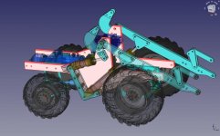
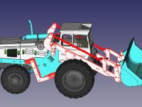
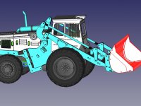
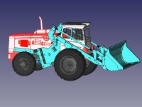
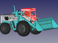
CAD work is close to be finished, the model is almost completely designed on 3D.

assembly-2023-05-30.jpg


Apart from cab and rear bumper (which is still on design phase) and hydraulics, the machine has been build and it is functional.

IMG_4805.jpg

IMG_4806.jpg

IMG_4804.jpg


The model is now RC so can be driven around, both locks (central and front diff) are working.

IMG_4807.jpg


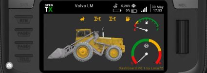
Even the Radiomaster TX16s dashboard is ready and working:

volvoLM841_radio.jpg


I worked a lot for this project in the last month and now I am taking a pause. Next step will be the hydraulics order to Magom.

Luca
 
Arms

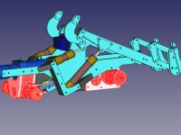
arms-CAD-01.jpg

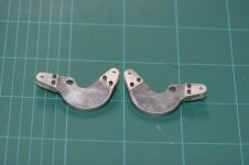
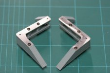
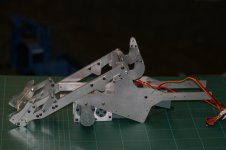
Arms design is quite original in this machine.I tied to replicate it copying quotes from a lateral drawing I found on the net (it was from a 1:50 model). I designed everything then I cut the ALU sheets as usual with my CNC router. I also designed PLA bushes and I printed them.

arms_03.jpg

arms_04.jpg

arms_05.jpg

arms_02.jpg

Unfortunately, the cylinder dimensions I choose for the bucket movement were not completely correct. I tried to simulate all movements, but in real life it turned out that at full arm lift the bucket was too much limited.

So I made further simulation and I found a working compromise. At the end a loose a little of parallel movement of the bucket: when I lift it tends to move downward. I could not find a better solution with the actual cylinder extension and I gave priority to bucket emptying.

I printed several arm parts to test for movements then, when I found the one combination that satisfied me, I cut the new parts with the CNC router.

Luca72
 
Bucket

bucket-CAD-01.jpg

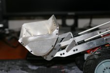
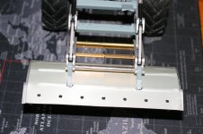
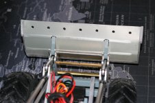
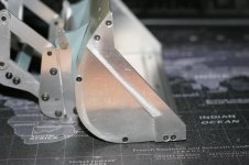
For this machine you can find dozens of different bucket types. I copied the one on the Volvo commercials and I made it slightly bigger. As I did with the CAT M318 excavator, I manually bended the rear panel. Unfortunately the bigger size of this bucket made it vey hard, but at the end I was able to complete the bucket and I secured it with a lot of M2 screws. Unlike the arms that took me a lot of tries, bucket came out as I wanted. Maybe a little too big, but I like it.

bucket_04.jpg

bucket_03.jpg

bucket_02.jpg


I copied the attach from a 841 machine that had hydraulic lock and I am going to implement that function later. I have to admit I regret a little, the choice... this way bucket is attached way too distant from the turning point ant it makes it look even bigger.

bucket_01.jpg


Luca72
 
Frame (2nd part)

frame_CAD_02.jpg

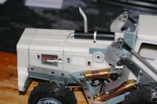
Once all functional parts (arm, transmission, steering, etc.) were printed or cut with the router, I finished the frame. First I designed the fake motor cover (that in the model is the battery compartment).

frame_battery_box_CAD_03.jpg


frame_02_05.JPG

frame_02_08.JPG


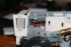
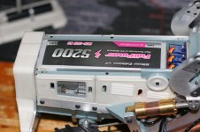
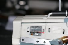
I wanted to mantein the possibility to remove panels so I designed it as a frame with the panel mounted using 3x2mm small magnets. The frame is also used to keep the battery in place and has some routing for the wires (pump motor and main 12V circuit).

frame_02_09.JPG


I used strong PLA for the frame and a high quality (but quite brittle) PLA for the panels. The latter has an excellent surface finish so I hope it will reduce painting times. At the end (as always with this model) I lacked space: 5200 mAh battery (I also use on CAT M318) would fit so tight that even a small difference of size between the two I have, made it impossible to close the upper panel....

frame_02_10.JPG

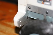
After struggling with the fake motor cover, I designed the rear bumper and the back of the motor cover. The bumper is empty inside because it will contain the iron counterweight. For this reason I made the attach to the main panel using ALU instead of PLA.

frame_02_07.JPG


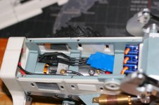
Also the motor cover back is empty, to contain the battery cable and plugs (which, in a 5200 mAh battery, are huge).

frame_02_06.JPG


Luca72
 
Hydraulics

hydraulics-CAD-01.jpg

Magom makes CAD files public for most of its hydraulics parts, so I could insert them in my FreeCAD projects and I had not to worry for size.

Once I was sure about everything I placed the order. It was a Sunday morning I I hoped to have the parts for the end of the next week. Magom really surprised me, because no more than 48 hours later I had the package at home. And it contained four customize cylinders.... I was really impressed!

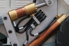
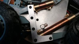
With the hydraulics part I could test all the movements and I found out (as I described in the Arms post) that I slightly miscalculated bucket cylinders. Nothing that could not be fixed with a little revision of all geometries.

I had to put my two frame halves again under the CNC router to carve the hoses holes. I also made a couple of hose holders for side and I fixed them with superglue.
Big problem was making the tubes bent at 90 deg where they come out from main frame. It is all very tight and even 3mm tubes seems enormous....

[hydraulics-01.jpg


Moreover I had to replace ALL hydraulic elbow connectors because they were WAY too big.

hydraulics-00.jpg


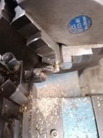
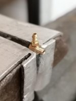
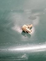
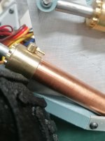
I used my lathe, 5mm brass rod and some leftover nipples from CAT M318 project and I made smaller elbow connectors. I also made tiny (I took no picture of them, unfortunately) "T" connectors at the exit of the hydraulic valves.

hydraulics_90deg_making-06.jpg

hydraulics_90deg_making-05.jpg

hydraulics_90deg_making-07.jpg

hydraulics_90deg_making-09.jpg


First test was a disaster.... Pump main tube elbow connector leaked a lot and a couple of cylinder tubes bending closed completely the oil flow. It took me some time and a some oil to sort everything out, but at the and I found a way to make everything work.

The valves were quite hard to actuate and the small servos were struggling. So I completely dismantled them and removed a shim for every valve. The hardness was probably due to the fact the valves were new and it would probably disappear with time. But since at the moment I do not see any loss of position when the machine is left off, I think I will keep them removed.

As with CAT M318 I am very satisfied with hydraulics. Once I sorted everything out I have no leakings, the pump has plenty of power for this kind of model so I can use it at very low rev level.

This is the BOOM for hydraulics (in case somebody wants to build this model):
- Valve 3-way V2 - 3mm tube Qt.1
- hydraulic hose Ø3x1.8mm mt 7
- Locking sleeve for 3mm hose Qt.25
- Hydraulic oil ml 500
- Spring for hydraulic hose 3mm Qt.2
- Micro servo 9g Qt.3
- Hydraulic pump M3 with integrated tank + brushless Motor Qt.1
- Hydraulic cylinder Ø15mm (56mm-79.4mm) - Star Qt.2
- Hydraulic cylinder Ø15mm (101mm-169.4mm) - Star Qt.2
- Brushless ESC 30A - ZTW Qt.1

You also need some nipples (about 30) to make elbow and T connectors.

Here a small video I made just after I sorted out all the hydraulic issues. In this video the bucket movement uses the old geometry and it is a little limited with the arm full up.

Um diese Inhalte anzuzeigen, benötigen wir die Zustimmung zum Setzen von Drittanbieter-Cookies.
Für weitere Informationen siehe die Seite Verwendung von Cookies.

Luca72
 
Hi Luca,
Your model looks great and it works very well. :like :klack

:winker
 
cab-CAD.jpg

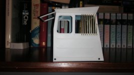
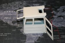
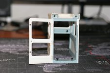
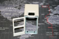
For every model I made I started designing the cab (exception made for CAT M318 wich uses Bruder cab), because it always was the troublesome part. But this time it was a simple and easy (ok, not so easy...) cab, to design. So I kept it for last. For a first, I made front door and rear window, openable. I used small hinges I found on the net fixed with micro screws for glasses.

cab-full.jpg

cab_04.JPG

cab_03.JPG

cab_01.JPG


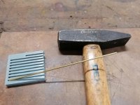
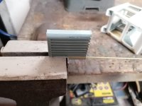
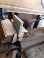
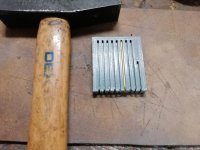
Most difficult part was to bend the brass wires for lateral protections. I made a small tool with 3Dprinter that made the whole process way easier.

cab-protections-process-01.jpg

cab-protections-process-02.jpg

cab-protections-process-03.jpg

cab-protections-process-04.jpg


The final result was very good (in my opinion, of course).

cab-protections.jpg


I made screw holes for the cab internals, but it will have to find place among the receiver and all the servo/esc wirings.

Luca72
 
Hi Luca,Your model looks great and it works very well.
Thank you :)

After sorting out some hydraulic issues (bent hoses), it seems to work as expected. In the next post, which concludes the pre-painting part, I will publish a video of the model in action.

Luca72
 
Good idea with the printed bending device. Thanks for reporting.
 

Servonaut
Zurück
Oben Unten