• Die Forumsregeln und Nutzungsbedingungen findet ihr in der Navbar unter Impressum !
    Bitte unbedingt beachten!
    Wie überall im Leben gibt es Spielregeln, so auch hier!
    Die Datenschutzerklärung zum DSGVO findet ihr ebenfalls in der Navbar unter Datenschutzerklärung !
    Hinweis nach DSGVO :
    Es ist hier keinerlei Angabe erforderlich. Alle Angaben in diesem Bereich sind öffentlich sichtbar und werden freiwillig gemacht. Mit einem Eintrag in diesem Bereich erkenne ich dieses an, und bestätige die Datenschutzerklärung zur DSGVO für das Forum gelesen zu haben.

    Danke

Bruder-Umbau Wheeled excavator CAT M318

Luca72

New member
Registriert
02.10.2020
Beiträge
92
As soon as I was finishing my first model (Mercedes AS 1838 4x4) my friend gave me a Bruder CAT 320d as a gift. I started imaging how to convert it but at the time I was not skilled enough for that.
The first idea was an electric conversion with self built cylinders and boom. Time passed, I got more skilled, I built other models but the Bruder was still to be converted...

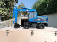
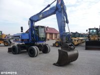
Until I came across this picture on the web:
916208855_8_1080x720_koparka-kolowa-_rev007.jpg

It was love at first sight and I decided that that was exactly how I wanted my conversion to become.

Since I had previously build a truck with electric cylinder I know exactly their limits (and also their strong points). I decided to go hydraulics :)

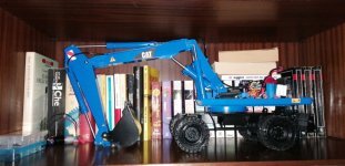
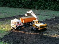
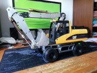
Project took me a year and half to finish it, but last Sunday I had the model ready to run :)
IMG_20201010_131627.jpg

Now that the project is finished I am open sourcing it (CatM318 on Luca72 GitHub). Cnc parts are still missing but I will upload them soon.

In the next days I will complete the thread with the building steps.

Luca72
 
Axles

After deciding it had to be a wheel excavator I started 3d modeling the axles with FreeCAD.
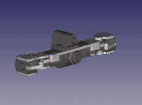
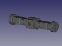
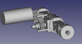
Luckily I found on the Web a couple of detailed pictures of both front and rear axle (this one with motor).
I decided to use a mix of printed parts and ALU parts. For the shells of the axles I used a special PLA overloaded with carbon fiber. Very strong and with a nice surface finish.
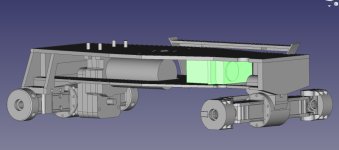
In this pictures you can see plastic parts (DARK) and ALU parts (light)

front-axle-CAD.jpg

rear-axle-CAD.jpg


I found a suitable sized differential in a Chinese Feiyue scaler model : Feiyue diff
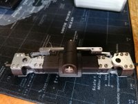
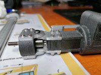
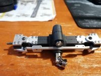
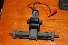
Very narrow with main parts and gears made of steel and ALU body For the rear axle I just cut and tapped the bars at the right width. For the front axle I decided to use Tamiya TLT rods and joints so I had to make a quite difficult work to adapt the Tamiya rod to the diff big gear. But at the end everything turned out very strong and functional:

Front Axle

IMG-20200702-WA0008.jpg

IMG-20200702-WA0007.jpg

IMG-20200702-WA0005.jpg


Rear Axle

DPP_0035.JPG


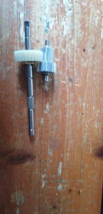
For the motor and the gearbox I used a 380 size High current motor at 500 (rated) RPM (2.7A ratio current and 16A :mama stall current) and Tamiya gearbox gears:
10T as pinion, 20T as secondary gear uf first stage of reduction then 13T and 27T as second stage of reduction.
Final reduction was about 1:4.

IMG-20200615-WA0013.jpg

IMG-20200614-WA0004.jpg


With a bit of luck (I bought two motors with different reduction ratio to be sure) the speed was perfect for a wheeled excavator.

The axles were the first part I produced then I dedicated various months designing the rest of the model and for a long time (about a year) I did not produce any other part.

Luca72
 
Zuletzt bearbeitet von einem Moderator:
Hallo Luca,

the steering of the front axle will not fit. The geometry doesn´t look correct. Please have a look at Ackermann steering.

Do you have a link to the chinese differentail gear supplier, they look well, even in size!
 
Hi Luca
Really cool excavator that you made. And I thing it's such a cool thing that you do this as a open source! You are the first IMHO. Looking forwards. I appreciate your work.
 
Hallo Luca,
the steering of the front axle will not fit. The geometry doesn´t look correct. Please have a look at Ackermann steering.
You are right, steering is not completely OK. Ackermann has been considered during CAD design, but the limited space (hub goes a long way inside the rim, until the external wheel rim) has made it almost ineffective

Here is maximum steering and inner wheel is just a (tiny) little more steered respect to external one
2020-10-15__12_34_36.JPG

But biggest problem here is that there is no central diff. I could no find it even in the real machine (first time I see a fixed transmission). Offroad it is not a problem and it is completely smooth, steering. But on high grip surface it does not steer very well.


Hallo Luca,
Do you have a link to the chinese differentail gear supplier, they look well, even in size!
You can find it on AliExpress: Feiyue FY-01 FY-02 FY-03 FY-04 FY-05 FY-06 FY-07 1/12 RC Cars Parts Upgrade front and rear differential box / Differential gear , Banggood or even on Amazon, sometimes. It is the rear diff for Feiyue crawler (also the front diff is OK, but has short rods)


Hi Luca
Really cool excavator that you made. And I thing it's such a cool thing that you do this as a open source! You are the first IMHO. Looking forwards. I appreciate your work.
Thanks, On my GitHub you can find all my models and they can be downloaded. I like to share, just in case somebody would find useful some of my works.


Regards,
Luca72
 
Hallo Luca,

thanks for the link. What kind of 3D design software do you use?
 
Wheels and rims

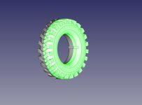
I absolutely wanted Bridgestone 11.00-20 offroad tires under my wheeled excavator. Since they are not available in this scale I decided to 3D print them.

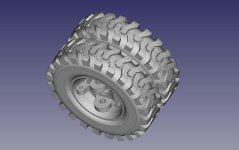
I designed them in FreeCAD. It was quite easy, since they have a repetitive pattern. I started with an height of 78mm which respect the 1:14 scale (excavator tires are usually a bit smaller than truck tires) bu at the end I found more aesthetically appealing having them at 80 mm height (more or less like standard Tamiya tires)

wheel-CAD.jpeg

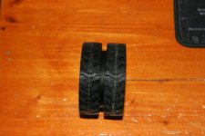
I designed them so that they can be printed in two halves and then glued together. This way I could have details in both sides.

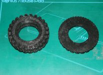
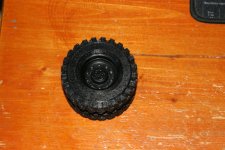
I used printable TPU trying two different stiffness: SHORE 80A (very soft) and 90A (a little bit hard). 80A is very difficult to print but gives very realistic results. But I had to print 16 halves (each one taking about two hours to print) and I could not allow too many failures. Thus, after various failed trials, I decided for the harder rubber: SHORE 90A.

It took about a week to have all 8 tires, but the results were (in my opinion) great, so I think it was worth it :)

Tires have four dents in the inside part to allow them to be aligned and glued easily on the rim. And to improve adherence between rim and tire.

2020-10-16__001.JPG


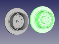
Rims were designed to allow hub to get quite deep inside so to have the front steering pivot inside the double wheel. I used PLA Layer (which is an high quality PLA with good surface finishing).
Results were nice, in my opinion:

Here rim can be seen from inside and outside (green). In the inside there is the cut for the front axle driven bar key (it has standard Tamiya 2mm rod)
rim-CAD.jpeg

wheel-001-CAD.jpeg

2020-10-04__11_21_58.JPG

Between the two tires I inserted a PLA spacer to prevent anything to get inside and get stuck (also the real machine has a big ring between the tires)

2020-10-04__11_22_06.JPG

Luca72
 
Design time

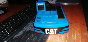
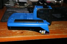
After finishing both axles and wheels. I took a long time to design the whole machine around the Bruder parts. After some thoughs I decided to discard boom, bucket, undercarriage (Bruder is tracked, so it is of no use on wheeled excavator), and the boom attach. I only kept the cabin and the upper body.

CAT M318 has been produced since the nineties and there are two very different versions. They differ both in body and in boom shape. The version I choose was the older one, like the first picture of this thread.

Quickly I designed the boom, scaling everything from original CAT datasheets. I took the width of the machine (2.50 mt) as fixed parameter as it scales exactly as tamiya trucks in 1:14 scale: about 190mm.
Then I printed the datasheet dimensions page and manually scaled everything else.


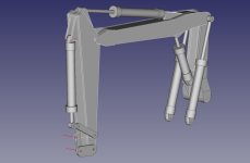
This is the boom as it was designed at the very beginning (some improvements has been made in the following months):

2019-12-31-WA0015.JPG


Then I designed the pistons so I could see how much all the parts of the boom articulates:

2019-12-19-WA0004.JPG


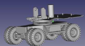
Next came the boom attach and the plate to reinforce the inside of the Bruder upper body. And little by little I designed the undercarriage, the boom (quite difficult, I have to admit it) and the geared turntable

2020-06-01-WA0005.JPG


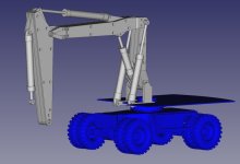
And finally boom, turret and undercarriage assembled:

2020-06-01-WA0004.JPG


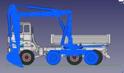
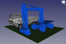
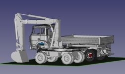
With the big part of the project done it was time to check (on "paper") how it looked like beside my trucks.
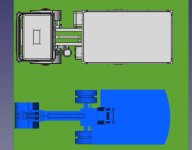
I decided to use the 3D model of my Iveco 250-30 6x4/4. Actually it has a crane with clamshell bucket, behind the cabin, but in this 3D model it is not present to keep it lighter.

Side view
2020-06-13-WA0005.JPG

Top view
2020-06-13-WA0006.JPG

Front side view
2020-06-13-WA0007.JPG

Rear side view
2020-06-13-WA0004.JPG

It seems OK and quite realistic in size. At this point I decided it was time to start cutting some parts. Design time was (almost) over. Now starts building time!!!!

Luca 72
 
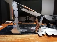
Boom construction

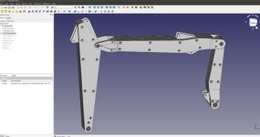
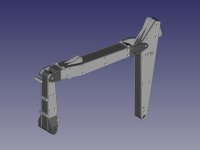
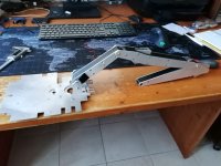
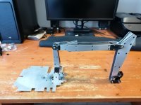
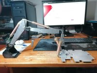
Boom was designed to be strong enough but very light (to be able to use a less powerful hydraulic system). It was made of ALU plates kept together by screws, hex bars and a 3D printed skeleton (which has only aesthetical function, since hex bars keep the structure firmly in place).

In the picture you can see the ALU parts (lighter) and PLA parts (darker)

boom-CAD.jpeg


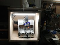
My small router CNC has been lying idle for almost one year and half since I bought it. Now it is time to make it work a little (here it is cutting a piece of the arm):

2020-01-25-WA0004.jpg


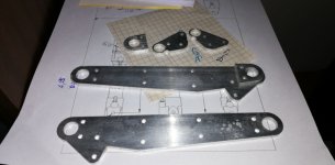
I bought some 3mm ALU flat bars (sized 50x1000 mm) from my local hobbyist store. They were perfect for making all pieces that formed the boom: first arm, main arm and second arm. Attach for pistons were made by ALU parts inside the printed parts and fixed with hex bars and screws.

Here is the first arm as it came just out of the CNC router:

2019-12-27-WA0008.JPG


Every hole here must be countersunk to allow the use of countersunk screws.

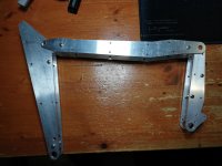
Little by little I cut all the ALU pieces for the boom, here is pictured after a first quick assembly. In the first and last arm, the hex bars that keeps the plates together can be seen (here I am still using standard screws, because countersunk work is still to be made). (funny note: when I took the picture I didn't notice, but first arm is mounted turned to the wrong direction ;( )

2020-01-05__18_37_34.JPG


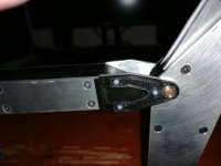
Following you can see the PLA parts mounted and the countersunk screws mounted:

2020-06-13-WA0002.JPG


Attach for the bucket required a first passage in prototyping material then (eventually) I cut it from ALU.

boom-bucket-attach-CAD.jpeg

2020-06-13-WA0003.JPG


Luca72
 
Hi, Luca,
Thank you for introducing us. I would be happy to get along with FreeCAD as well as you do.
The cabs and other models at github look interesting as well.
Greetings
Milan
 
Hi, Luca,
Thank you for introducing us. I would be happy to get along with FreeCAD as well as you do.
The cabs and other models at github look interesting as well.
Greetings
Milan
Hi,
FreeCAD can be used in several ways. You can design following standard rules: you draw your part on a 2D sketch then you extrude it. This gives you max versatility and if you need you can change the sketch and all the 3D extruded parts reflects your changes. This is the most professional (in my opinion) way to use FreeCAD. But it is the most difficult. And I have to admit I almost never use it.

In FreeCAD you can ADD and SUBTRACT primitive geometric forms (cylinders, cubes and so on) and you can Fillet or Chamfer every edge. This is the way I use FreeCAD. I set a Cube, I modify dimensions, I place some cylinders when I want the screw holes, then I subtract. Easy and quick. You can design your own primitives (hexagons, octagons, triangles, etc.) and you can extrude them. You can isolate two faces and Sweep your extrusion from one to the other.

I designed my first three models this way and they came out nice (you can see the 3D model of my Iveco 250-30 AHW in one of the post above: it is all made of ADDS and SUBS of cubes and cylinders, even the cab).
CAT M318 boom is designed using sketches, but it was a long and difficult job. At the end, for all other parts, I used basic ADDS and SUBS.

Greetings,
Luca72
 
Hi, Luca,
In the beginning I had also placed blocks and cylinders. Mostly via the keyboard, because the positioning functions do not like me.

In the meantime I have created the first simple parts by means of sketches.

The handling is totally different from Robcad or Turbocad 2D. I still have to practice a lot until it is enough for really complicated parts in a short time.

Regards
Milan
 
Bucket

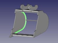
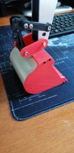
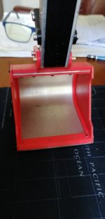
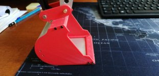
Bucket was quit difficult to design. I started copying Bruder bucket, but the results on CAD did not appealed me. So I turned to a shape similar to the one that Magom sells. I decided for this one.

bucket-CAD.jpeg


As usual (with difficult parts) I started witho prototyping it with 3Dprinter, exception made for the back plate theat I created from the beginning using ALU 0.75mm (formed by hand, with the help of the vise):

2020-06-16__12_30_21.JPG

2020-06-16__12_30_41.JPG

2020-06-16__12_30_56.JPG


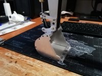
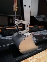
I was completely satisfied with the results so I cut the ALU parts (in the back I used a 3mm rod, with 2mm screws to keep the back plate in position)

2020-07-02-WA0002.JPG

2020-07-02-WA0003.JPG

Tooth remained made of PLA. I had planned to cut them from a 10x20mm ALU bar, but after first tests PLA ones were really strong, so I decide to give them a chance)

Luca72
 
Upper body reinforcement and Turret

For this part I heavily took inspiration from this thread: Conversion - CAT 320 CL.

First I cut the Bruder upper body as shown in the thread, the with paper I designed the shape of the body reinforcement. I made it in two parts, the lower one (inside the Bruder smaller shape) 3mm thick and the upper one 2mm thick. Then I prepared the holes for upper rotating bearing and rotating motor (380 size). Turret was designed very similar to the one of the thread above (that is Magom turret)

body-reinforcement-and-turret-CAD.jpeg


Then I cut the ALU parts and assembled them:

2020-06-13-WA0001.JPG

2020-06-06-WA0001.JPG

2020-06-13-WA0000.JPG

First arm was attached using two 13x5x4 bearings. Initially the rod remained inside the turret side panels but, at the end, I made holes and I used a passthrough rod as I did for all other boom joints.

At the end every thing fit nicely in place in the Bruder upper body :)

2020-06-16-WA0001.JPG


Luca72
 
Hydraulics

Hydraulics
Once the boom and the upper body were ready it was time to get the hydraulic system.
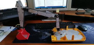
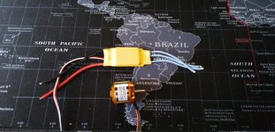
At the beginning I planned to build everything by myself, using the small router and the lathe for the cylinders.I even went so far to buy the copper tubes, the brass rods for the caps and even the brushless motor and regulator for the pump.

2020-06-06-WA0003.JPG


But when was time to start I thought about it for a second time. Building all the hydraulics meant months of try and check, a lot of wasted material and no guarantee on the results. And I was not even sure I had the skills and the tools mo make everything.

So I decided to buy everything. My choice was Magom because it was cheaper and had may ready kits for Bruder conversion. Since my model was a mix of ALU and printed plastic, boom was quite light (but the model respects the scale weight) I did not need too much power.

I calculated all measures for the cylinders. This was the BOM of my order:

1x Hydraulic cylinder 15 mm M3 - star - TYPE 2: 111 mm
1x Hydraulic cylinder 15 mm M3 - star - TYPE 3: 111 mm
2x Hydraulic cylinder 15 mm M3 - star - TYPE 4: 132 mm
1x Hydraulic cylinder 18 mm M3 - TYPE 5: 80 mm
1x Hydraulic pump brushless M3 with integrated tank - Tank length : 70 mm
1x 4-way Valve M3 V2
6mt 3/1.8mm hose
26 Locking sleeves
500ml Hydraulic oil
4x 9g servo HXT900
Various spare parts (o-rings, nipples, etc.)


Material took about a week to be prepared (cylinders were custom sized) and (UNBELIEVABLE) little more than 20 hours to get from Spain to my house in North Italy. Following tracking, package was picket up in the afternoon and arrived at my door the next morning. GREAT.

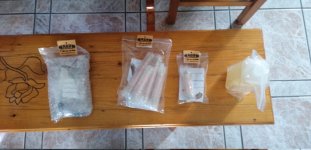
Here is the material just out of the package, few minutes after I received it.

2020-06-17-WA0002.JPG


Nothing was missing and I found that even though I ordered the pump without motor (I already had it) it was present and assembled.

It was time to mount the cylinders and see if everything articulated properly (and, of course,to have a first look of the model as it was turning out).

2020-06-17-WA0019.JPG

2020-07-02-WA0004.JPG


I was VERY happy with the look of the model with cylinders mounted. It really was as I had imaginated it.

Luca72
 
Hi, Luca,

I like the combination of the printed parts with the aluminium parts.
The fact that your report is not in German will probably cost you some answers.

For those who would like to know the answers I can recommend www.deepl.com.

Regards
Milan
 
...
I like the combination of the printed parts with the aluminium parts.
...

Hi,
thanks for the reply.

When I started with modelling (in the year 2013) I wanted a Tamiya truck and I had a 3D printer that was doing nothing. So I decided to give it a try and started building my first model, a MB 1838 4x4 tractor with two axle tipper semi-trailer (cab is from Tamiya: I bought it from Japan).

2020-08-08-WA0011.JPG

I was not sure that the mix of metal and printed parts could endure hard work, but after 7 years it is still working as when it was new. PLA is a very strong and rigid material (but you have to print in the right direction) and nowadays there are a lot of wonderful special filaments.

...
The fact that your report is not in German will probably cost you some answers.
...
Unfortunately I do not speak German. When I subscribed to this forum I had two choices: writing down in Italian and then translating everything with Google translate or ask permission to write in English (that I speak and write). I decided for the last one and I asked permission to the administrator before posting. This gives me more control on the final result. I keep Google translate active on the whole forum so I have everything translated in English without the need to do anything.

Regards,
Luca72
 
Undercarriage

With boom, upper body with cylinders and axles done, only undercarriage was missing for testing the model. Finishing it was another matter, since blade was still to be designed, electric system was still to be done and finally everything had to be painted.

But once the undercarriage was ready I could try some digging :)

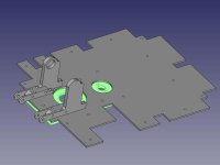
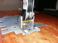
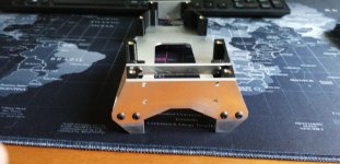
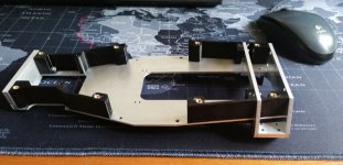
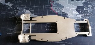
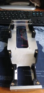
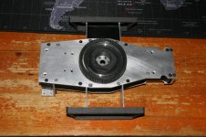
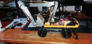
Undercarriage was quite simple: two ALU plates 3mm thick top and bottom, assembled with 20mm hexagonal brass bars (the same I used for boom), 3mm ALU plate for back and 5mm ALU plate for front. In the middle (with mostly aesthetical function) printed side walls. Front axle is mounted swiveling and rear axle is fix and screwed on 5mm ALU supports.

2020-06-25-WA0010.JPG

2020-06-25-WA0008.JPG

2020-06-25-WA0012.JPG

2020-06-25-WA0014.JPG


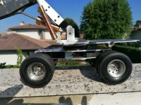
Fitting the steering servo was not easy, there was really little space.

2020-06-15-WA0014.JPG


Articulation of the steering bar was not OK, so when the fron axle swiveled, the steering anlge changes. Not good, but since it is a slow model I suppose it will not be a great problem.

Rear blade was still to be designed and given the very little space inside the chassis motors had to be moved inside the blade. We will see....

Turning gear was 3D printed with PLA overloaded with carbon fiber.

2020-10-04__11_23_10.JPG


Now that all the main parts are finished, model is ready to be assembled and hydraulic tubing to be laid out.


Luca72
 
First Assembly

Assembling all part was not difficult. First I connected the upper body to the undercarriage through the turning table:

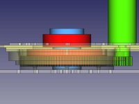
turntable-CAD.jpeg

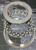
The red parts are the upper (42x25x11) and lower (70x50x14) thrust bearings :

2020-10-16__002.jpg


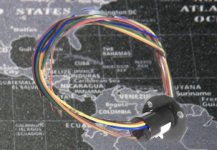
The blue part is a ALU part I created with lathe that attach firmly in the undercarriage via six M3 screws and keeps packed the bearings and the upper body. Inside there is the hole for the slipping ring (8 wires, 10A).

slip_ring_8wires_10A.jpg

Turning motor has changed so may times I lost the count. Finding right gear ratio and motor power was really hard (right power, too fast; right speed, too weak :sauer ) Finally I found a 37 RPM HIGH current (but not highest, more like 10000 RPM) motor that fit nicely. Gear ratio is made up by 100T (big rear fix on undercarriage) and 20T (motor gear) so final ratio is 5:1.

Here is the model just assembled:

2020-06-26-WA0006.JPG

2020-06-26-WA0008.JPG


Size compared to MB 1838 AS 4x4:

2020-06-26-WA0007.JPG

2020-06-26-WA0009.JPG


Time to lay out hydraulic tubing :hfg , finally. This was my first time with hydraulics but, honestly, it was not so hard. Connecting everything took me little more than one hour.

2020-07-18-WA0001.JPG


I made a first quick electric circuit and then I was able to make the first oil filling.

2020-08-22-WA0004.JPG


Everything went smoothly, with no leaking. Even the brass tubing on the first arm did not leak. GREAT.

Here is the first picture fully assembled and ready for first test:

2020-08-01-WA0002.JPG


Luca72
 
Finally digging

Here is the very first test, filmed under my porch

In this test wheels where still Tamiya's. Shortly I will change them for the printed ones.


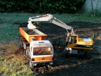
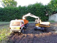
Time to dig some real earth:

2020-08-08-WA0014.JPG

2020-08-08-WA0012.JPG

2020-08-08-WA0013.JPG

2020-08-08-WA0011.JPG


Here a short video digging some hearth


In the next days I prepared some small upgrades and I replaced the wheels with the printed ones:

Battery opening cover and small modify to Bruder body (CAT M318 bonnet is continuous on thew right side)

2020-08-08-WA0002.JPG


New "shoes" :hfg

2020-08-01-WA0003.JPG


And finally another video with all upgrades mounted:

Um diese Inhalte anzuzeigen, benötigen wir die Zustimmung zum Setzen von Drittanbieter-Cookies.
Für weitere Informationen siehe die Seite Verwendung von Cookies.


Video shows very clearly the main issue of this model: tilting axle does not lock tilting when digging, so it is not very stable. Tilting lock is very hard to implement in the little space of the undercarriage. It is still to be implemented today. I would like to use two self made pistons on axle side and oil passing through a valve. Once locked the valve, tilting should lock. But fixing the cylinders is all but easy. We will see....


Luca72
 
Hi Luca,

will he still get a dozer blade with which he can support himself? Like the original?
It might be easier than locking the axle.

You had written that you have been printing for a long time. Does PLA become much more fragile over the years? Or did you not have a problem with it until now?

Regardas
Milan
 
...
will he still get a dozer blade with which he can support himself? Like the original?
...
Yes :) , I will introduce it in the next post

2020-10-07__23_51_56.JPG


...
It might be easier than locking the axle.
...
It was what I thought, but... It did not work :( Tilting axle is always the weak point. If I lower the blade and keep the front axle in the same direction of the boom then OK, but if I dig in reverse side (like they do with the real machine) using blade as a stabilizer, it does not work since weight gets to the steering axle in the rear.


...
You had written that you have been printing for a long time. Does PLA become much more fragile over the years? Or did you not have a problem with it until now?
Even the very first parts I printed in 2013 are perfect (I still have most of them, even those parts I upgraded). No sign of wearing down or getting more fragile. No problem at all with PLA.
Since it is quite inexpensive, at beginning I thought it acceptable to print most important part every 3/4 years, but so far no need for that.


Regards,
Luca72
 
Blade

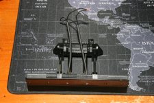
The last part I designed was the blade. The most difficult problem I had to resolve was the really small size available for gearmotors. Athe the end I decided to put the motors INSIDE the blade body (luckily it is a BIG blade even in the real machine). This means I have to use bevel gears to couple the motors (that are mounted at 90 degrees) to the "cylinders" . I found a couple of bever gears on GHW Modellbau 20T and module 0.5. With a diameter of 10mm they fit perfectly in the low side of the blade. I used two Pololu HP 1:50 Micro Gearmotors one for each "cylinder" but coupled with a passthrough rod to avoid difference of speed

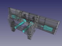
blade-002-CAD.jpeg


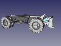
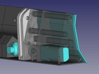
This is how the blade looks (in 3D CAD modelling) mounted on the chassis. As usual light parts are made of ALU and darker ones are 3D printed with PLA.

blade-001-CAD.jpeg


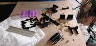
This is the most complex part of the model and it is made by a lot of parts:

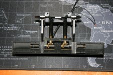
2020-09-21-WA0008.JPG


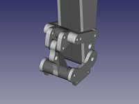
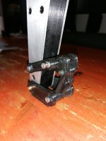
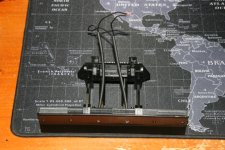
The front part of the blade is manual made from a sheet of ALU 1mm and bent with the help of the vise. The inner skeleton of the blade is made by ALU parts connected by brass 4mm rods, tapped for 3mm screws. The PLA body has carving to allow them to be positioned. This way PLA has only decorative funcion and keeps the two motors in place.

blade-004-CAD.jpeg


Once assembled it looks like this:

2020-10-07__23_51_39.JPG

As can be seen "cylinders" are simply brass rods (10mm) internally tapped (M5) with a M5 wormscrew moved by the bevel gear.

2020-10-07__23_51_56.JPG


The four arms uses small bearings (7x3x3mm) to attach to blade and chassis and are reinforced with two ALU rods in the lower and in the upper pair of arms.

blade-003.jpeg


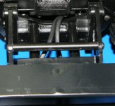
As can be seen in the last picture, gears are protected from soil, dirt, etc., using adhesive tape fixed in position using double side extra strong adhesive tape. It allows for the movement of the cylinders and keeps the area clean.

Luca72
 
Painting (or let the nightmare begin)

Painting is something I am not able to do. No excuses, I am a total ZERO :( But a model has to be painted, so this phase eventually arrives. And, as usual, it is a real nightmare, for me. Because everything can be ruined by I wrong made painting. No matter how much work it took to get to this point, nice painting is... let's say 50% of the whole?

Anyway, stop philosophizing about painting and let's get into the real operation.

But before starting with spray can, I had to find the color I saw in the real model (it can be seen in the first post). That wonderful blue that (of course) is not from CAT. It was much more harder than I expected, because no color shop wanted to make me a color based on a picture. None :(

So I started looking around the net looking for a matching blue. RAL5005 (signal blue) was the closest match, but it was not it. With no other options I started making research on the specific machine of the picture. unfortunately it probably had been sold in the meantime so I could not find any hint on the website that published it, because it was already disappeared...
I had luck with a name on the side of the body, HUTHMANN: it turned out it was a NEW HOLLAND reseller. And it turned out that New Holland Blue was a perfect match for the color I was looking for. New Holland has a reseller few kilometers away from my house, so buying it was extremely easy
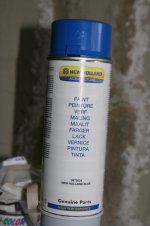
2020-10-04__11_20_35.JPG


With the main paint found, I choose "semi gloss black" for chassis and bucket and "Tamiya semi gloss clear" for fixing decals ink.

And painting could start. First came the yellow Bruder body. I soon discovered that solvent in the paint slightly dissolved the yellow in the plastic and part of it got into the blue making it slightly greenish.. I had to do the work twice on the plastic part (and it got slightly damaged from this work). At the end I found a way to paint it. But it took many days to have an acceptable final look.
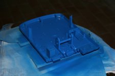
2020-10-04__11_17_12.JPG


To hide the holes of the screw I applied a vinyl adhesive sheet on the side of the arms. It was an A4 sheet of vinyl made for inkjet printers (the same I used to make decals) so it was very easy to paint over it. Final results were good and screws were well hidden under this layer.
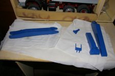
2020-10-06__08_55_36.JPG


The same I did for the chassis.

On ALU parts I applied a primer for light metals, but It did not do it work very well. Final result on ALU parts was a very fragile paint that is easily damageable.
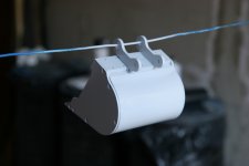
2020-10-06__08_54_34.JPG


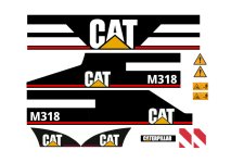
Decals were made from scans from original Bruder decals and some other picture downloaded from the net. I made a A4 picture ready to be printed on adhesive vynil. To fix the colors I used "Tamiya semi gloss clear" that gave a nice semi gloss finish very similar to the other paint of the model.

Here is a small size copy of the decals file. The full sized one can be found on my GitHub.
full_decals.jpg

Decals give a very nice touch to the model, I like very much the final results:
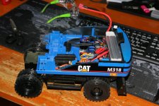
2020-10-08__16_08_04.JPG

2020-10-08-WA0009.JPG

2020-10-04__11_24_38.JPG

2020-10-08-WA0005.JPG


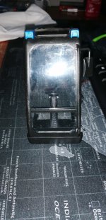
During painting I also applied windows glasses at the cab and a steering wheel replaced the two levers for tracks:
2020-10-08-WA0007.JPG


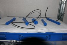
Cylinders were painted too and I applied paint also on the part of the tubing that goes from the tip of the cylinder. Just to simulate the real metallic tubing. With the CNC router I made a very little tubing passthrough that I applied at the opposite end of the cylinder (it keeps the tubing in place and parallel to the cylinder)
2020-10-06__08_55_54.JPG


With painting FINALLY done (with acceptable results) my model is FINISHED.
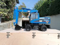
2020-10-10__13_16_28.JPG

Luca72

P.S: In the next days I will add some posts that integrates some steps of the building I overlooked and I will add a kind of Bill Of Materials just in case somebody were interested in building some parts or even the full model.
 

Servonaut
Zurück
Oben Unten