• Die Forumsregeln und Nutzungsbedingungen findet ihr in der Navbar unter Impressum !
    Bitte unbedingt beachten!
    Wie überall im Leben gibt es Spielregeln, so auch hier!
    Die Datenschutzerklärung zum DSGVO findet ihr ebenfalls in der Navbar unter Datenschutzerklärung !
    Hinweis nach DSGVO :
    Es ist hier keinerlei Angabe erforderlich. Alle Angaben in diesem Bereich sind öffentlich sichtbar und werden freiwillig gemacht. Mit einem Eintrag in diesem Bereich erkenne ich dieses an, und bestätige die Datenschutzerklärung zur DSGVO für das Forum gelesen zu haben.

    Danke

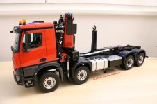
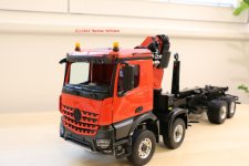
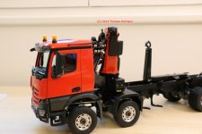
ScaleArt BB - Arocs 8x8 Abroller mit Palfinger Kran

Mein Traumfahrzeug!
... die Jungs von ScaleArt abgeraten haben, mit diesem Fahrzeug zu beginnen ...

Scaleart hat mich auch auf die Komplexität dieses Fahrzeuges hingewiesen, aber nachdem ich nur Modellzusammenbauer bin, wollte ich zumindest diese Herausforderung annehmen ;)

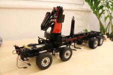
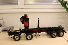
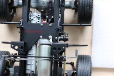
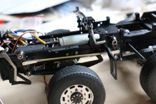
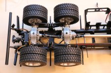
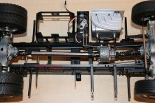
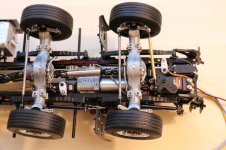
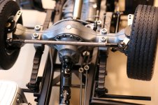
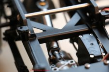
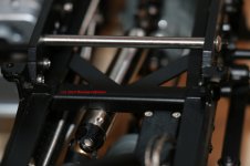
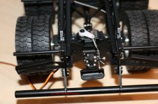
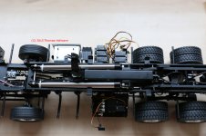
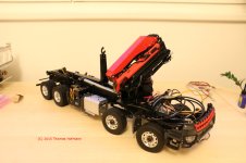
DE: mal ein Fast Forward einlegen - der Aufbau der Achsen/Kotflügel bzw des Abrollaufbaus ist schon zahlreich dokumentiert, also habe ich diesen Teil der Fotostory ausgelassen und zeige mal, wie die Kombination aussieht. Zur Komplettierung des Unterbaus benötige ich die Kardanwellen und die Hydraulikservos :/ Trotzdem hat mich die Neugier gepackt, wie der LKW aussehen könnte ...
Für den genauen Leser: die Felgen an der 2.HA werden noch ersetzt, hier wurden statt der HA Felgen VA Felgen geliefert ...

EN: using the fast forward mode in this photo story - assembly of the axles, fenders and roll-on/off tipper have been already documented, so i skipped those (pictures exist and can be shared/added upon special interest) - still i was quite curious how the crane looks on the chassis. to complete the later i am still waiting for the drivetrain and die hydraulic servos, but again i coulnt resist my own curiosity ...
For the readers keen on details: the rims on the last axles will be replaced to match the other ones - there was a glitch on the shipping and i received fron instead of rear rims ...

IMG_7092.jpg
IMG_7093.jpg
 
Hi Tom,
jetzt kommt die "Wuchtbrumme" Palfinger neben dem "popeligen" Abrollaufbau erst richtig zur Geltung. Wenn man ganz genau hinschaut, sieht man förmlich, wie Vorderachse einfedert. ;)

Vielleicht wird es zum nächsten oder über- oder überübernächsten :nks mit meinem Truck ja auch noch was. Erst beschäftige ich mich noch ein bisschen mit meinem Trostpflästerchen, das ich mir nach der „Absage“ von ScaleArt gegönnt habe :trucker

LG Michael
 
Moin Moin
Das gibt einen heftigen Brocken , wenn er mal fertig ist ! 4 Achs Abroller habe ich von ScaleArt schon den einen oder anderen gesehen , aber mit Ladekran :mama ...... ! Auf dieses Modell müsste ich warscheinlich die nächsten 15 Jahre sparen :cool , Michael
 
@ Michael ( Dampfmichel) - ich muss meine Wartezeiten auch immer überbrücken ;)
@ Michael (Maytruck) - das Gewicht ist wirklich beeindruckend ...

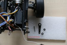
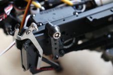
DE: Habe ein paar freie Stunden zum Weiterbauen genutzt ... Den Beginn macht die Achsanlenkung
EN: used some spare time to continue the assemlby - lets start with the front axles connection rod

IMG_7104.jpg

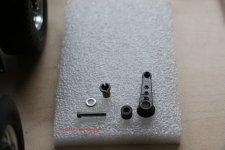
DE: in die Befestigung habe ich einen Schlitz gefräst
EN: to ease a later assembly / disassemble i did some milling

IMG_7107.jpg
IMG_7108.jpg

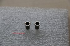
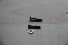
DE: die Original vorgesehene Imbusschraube habe ich durch eine Sechskantschraube mit Beilagscheibe ersetzt: Hintergrund ist der verwendete Hilfsrahmen für den Kran, der zuwenig Platz für die Imbusschraube bietet
EN: due to the extra frame for the crane i had to change the screw types: the one planned originally doesnt fit in the given space. in addition i used a washer as well

IMG_7112.jpg
IMG_7113.jpg

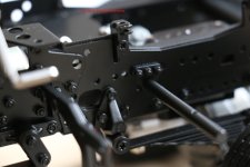
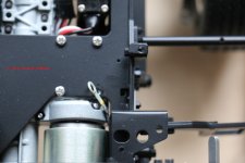
DE: Detailaufnahme der Halterung
EN: detailed view, where the previously pictured items will be fitted to the frame

IMG_7115.jpg
IMG_7116.jpg

DE: Aufgrund der Federung der 2. Vorderachse musste ich noch weitere Beilagscheiben verwenden, jetzt bewegt sich die Anlenkung einwandfrei
EN: i had to use 2 additional spacers to ensure that the connection rod doesnt conflict with the springs of the second front axle

IMG_7117.jpg
IMG_7120.jpg

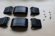
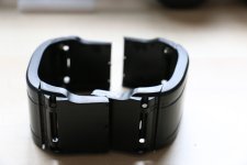
DE: Zusammenbau des vorderen Kotflügels
EN: front fender assembly

IMG_7121.jpg
IMG_7123.jpg
IMG_7125.jpg

DE: auf der linken Seite muss der Kotflügel wegen der Achsanlenkung eingeschnitten werden
EN: parts of the left fender has to be removed due to the connection rod

IMG_7126.jpg
IMG_7128.jpg
IMG_7131.jpg

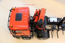
DE: Premiere: Hütte und Kran zum ersten Mal gemeinsam auf dem Fahrgestell
EN: cab and crane residing for the first time together on the chassis

IMG_7132.jpg
IMG_7133.jpg
IMG_7134.jpg

DE: die Farbe passt ideal zusammen - jetzt heisst es warten bis die fehlenden Teile eintreffen, damit ich das Chassis komplettieren kann - das Gewicht ist jetzt schon beeindruckend ... inzwischen gehts mit dem OPA - dem SK weiter ...
EN: the color of the can and the crane fit well together - once the missing parts arrive, i will complete the chassis - the weight is already quite impressive ... the waiting time will be used to continue with the SK tipper build ...
 
Hallo Tom,

das wird wirklich ein imposantes Fahrzeug. :ok

Beim Farbton des Fahrerhauses liegen wir ja mittlerweile auf gleicher Linie. ;) Ist das originale Palfinger-Rot der gleiche Farbton, wie der des AROCS oder hast Du den Kran im Farbton des Fahrerhauses lackieren lassen?
 
Bis jetzt habe ich nur heimlich mitgelesen und Bilder geschaut. Aber ich muss sagen ein imposantes Modell mit einem hohen Spielwelt. Bekommt der Kran noch ein Greifer??
 
The truck looks nice :ok
Wouldn't it be better to have turned the crane 180 degrees,
with the boom facing backwards.

Also thanks for writing in English as well :ok:ok
 
DE:
@Christian: nein, ich denke es war einfach "Glück" und in der Form ursprünglich nicht geplant - Original sollte der Arocs ja ein Dreiseitenkipper werden, aber dann kam dieser Drang nach dem Kran ...
@Pasci: ja es soll noch ein Schwenkwerk und ein Greifer kommen
@torarne81: Der Kran ist aktuell aufgesetzt, wie vorgesehen

Ich werde zur Orientierung einige Bilder vom Modell meines Kollegen machen, damit ich eine Idee zur Verlegung der Leitungen entwickeln kann

EN:

@christian: the color match was just by coincidence, but overall i was lucky ... the original plans for the arocs cab would have resulted in an 8x8 tipper
@Pasci: yes accessories are planned, but not yet available - i will order them once available
@torarne81: the crane and its boom is mounted (not secured yet) like recommended: will check the overall situation before final mounting .. part of the operating instruction is a separate crane folding instruction

will take more picture of my clubs colleagues model to figure out the layout of the pipes and cables
 
Hallo Tom, :winker

WOW

war seit ein paar Tagen nicht hier im Forum und schon habe ich was verpasst.

SUPER :ok:ok:ok

Ein Modell nach meinem Geschmack. :heilig
 
Servus Thomas,

Die Idee ist schon echt krass und er wird monströs! Da bleibe ich mal dran......:ok:ok
 
Echt ein starkes Teil... da kommt sofort der "Haben will"-Effekt hoch :)

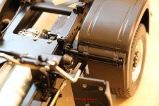
Ein kleine Manko konnte ich aber noch finden: Die Verbindungsstange zwischen den beiden Hebeln der Lenkung schaut so unschön farbig aus dem Radhaus heraus... machst du diese noch schwarz? Würde sehr viel besser aussehen, denke ich. :winker

Gut beobachtet - klar wird diese Hülle noch lackiert
 
Tom hast Du bitte eine Foto von mit der Seitenansicht Deines LKW. Bitte den LKW komplett ablichten. DANKE!
:ok
 
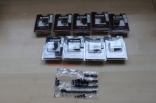
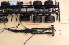
update: servos, kardanwellen und kingpus lichtkomponenten sind eingetroffen ... Also geht es mit dem Bau weiter.

gestern habe ich den Unterbau komplettiert, die Sperren verlegt und ewig mit der Lage der Bowdenzüge getüftelt... Ganz zufrieden bin ich noch nicht.

Zudem: das Schaltservo muss wegbegrenzt werden und die Anlenkung habe ich auch noch nicht zufriedenstellend gelöst..

Bilder kommen später (vorausgesetzt das Fahrgestell fährt, wie es soll) ...

@all: danke für den bisherigen Zuspruch
@erwin: dein Bild stelle ich dann mit ein ...

Ps: das Fahrgestell ist schon ohne Kran, Hütte bzw Abrollaufbau schwer ....

EN section follows:

Last week the remaining parts arrived, including the missing servos, drive train and kingbus light system. Yesterday i spent the whole day figuring out the best layout for the bodencable(s), still i am not completely satisfied yet. The same applies for the switching and steering servos :/

Hopefully i can share pictures later - assuming that i completed the chassis ...
@all: thanks for the positive comments so far

Even without the cab, crane and the roll on/off tipper the chassis weight is imprssive ...
 
DE: und weiter gehts ...
EN: the story goes on ...

IMG_7542.jpg

DE: Antrieb komplettiert:
EN: drive train completed:
IMG_7557.jpg
IMG_7558.jpg
IMG_7560.jpg
IMG_7564.jpg

DE: nach dem ewigen Bowden Zug gefummel, stand auch ein erster Fahrtest an ... dabei wäre es fast zu einer Katastrophe gekommen (das Chassis wollte vom Tisch in die Weite welt fahren - Ursache: ein falsch programmiertes Auswertemodul ... danach auf den Boden gesetzt und gefahren und ein fürchterliches Fahrgeräusch ... die Ursache war auch schnell gefunden...

EN: after spending hours on the bowden cables and the wiring i decided to go for a test drive ... due to a human error the chassis almsot drove of the table :/ after verifying the receiver settings i put the chassis on the floor and experience weired sound while driving ... the root cause was shortly identified:

IMG_7555.jpg

DE: und so sollte es aussehen:
EN: thats how it should look like:
IMG_7570.jpg

DE: die rockinger wurde auch noch mitangeschlossen ... hier war für die aufmerksamen Leser auch noch ein Fehler versteckt (auf dem Bild noch zu erkennen, mittlerweile aber korrigiert)
EN: the rockinger got wired as well .. for the readers - another glitch - on the picture it is still visible, but got fixed afterwards ...
IMG_7572.jpg

DE: die vorderen Beleuchtungsplatinen wurden durch Kingbuskomponenten ersetz
EN: the front lights got replaced with Kingbus components
IMG_7596.jpg
IMG_7598.jpg

DE: Hochzeit Abrollaufbau und Chassis
EN: roll-on/off tipper and chassis become one
IMG_7590.jpg

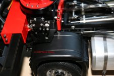
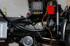
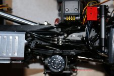
DE: wichtig - bei diesem Modell kommen andere Schlauchpositionen und Längen (Kippzylinder) zum Einsatz !!!
EN: IMPORTANT - the hydraulic tubes have diffferent positionions and lengths !
IMG_7607.jpg
IMG_7608.jpg

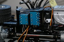
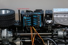
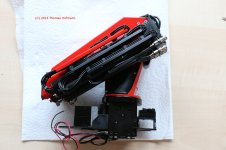
DE: die Ventile für den Kran
EN: the hydraulic valves for the crane
IMG_7611.jpg
IMG_7613.jpg
IMG_7619.jpg
IMG_7621.jpg
IMG_7623.jpg

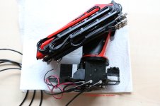
DE: Kranmontage ... eine Schraube der Getriebebefestigung habe ich entfernt, die andere durch eine Senkkopfschraube ersetzt
EN: mounting the crane ... i removed one screw securing the gearbox and for another one i changed the screw type

IMG_7625.jpg
IMG_7627.jpg
IMG_7628.jpg

DE: eine Ewigkeit später ...
EN: hours later ...
IMG_7629.jpg
 
Hi Tom, thank you very much for showing us this wonderful kit! :sabber

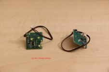
I notice that they changed the LED boards of the front lights too. Christian's ones got a different shape.

My fingers are hurting just looking at the multiple hoses that need connecting.

Cheers!
Stephan
 
Hi Tom, thank you very much for showing us this wonderful kit! :sabber

I notice that they changed the LED boards of the front lights too. Christian's ones got a different shape.

My fingers are hurting just looking at the multiple hoses that need connecting.

Cheers!
Stephan

very well said: while fingers hurts my head is still thinking, where to hide the additional 10 pipes connecting the valves with the crane.
praying every night that all the screws are secured enough and no leaking on the crane itself.
 
Hi Tom,
ick ka... ab! Wo ist bloß mein Sparbuch?
Fast genau so stelle ich mir meinen Truck vor. Ein bisserl röter (RAL 3000) aber sonst :ok

Mach weiter so!
LG Michael
 
Hi Tom, apologies for writing in English, but my school German not up to what I want to ask.

Am I right in thinking that your truck only uses one oil tank for the Roll on/off part and the Palfinger?

You have the 5 extra servos, can you connect those to the CM-5000? Just wondering since on my Roll on/off truck I have 5 free channels, but then no room for the BEC.

If you are worried about leaks, a bit of Loctite 542 really works.

Your truck is such a beautiful piece of engineering I could look at the pictures forever.

Regards!

Stephan

Stephan - no worries ;) i will respond in more details ...

in general i have to confess that there is quite some effort involved in taking the pictures, uploading and creating the updates here .. shame on me i should spend more time in giving lengthier explanations to the readers.

so as for your question: i am not using the scaleart commander, but will use brixl (i started with brixl and afterwards my whole club converted to brixl as well. initially i planned to use a 20channel receiver from brixl only. after figuring out the amount of tubes i have to connect between crane / valves and the pump, i adapted my plan: i will modify the tank (where you can optionally mount the speaker) to hold a 12 channel receiver: this one will serve all the hydraulic servos (7) + the rockinger (1) and two for the differential locks, totaling to 10. this receiver will be connected by 4 wires with the 20 channel receiver being placed in the cab and prevents me from connecting 10 servo lines through the whole truck. i also checked with brixl about the bec included in the 20 channel receiver and it should be sufficient for my plan ..

for the oil tank: yes only one tank for the roll on-off part and the crane itself: i am trusting scaleart that the volume is sufficient and if not - i could still attach a spare tank.

yes i am really worried about leaks especially due to the amount of connections ... thanks for the recommendation of loctite: i will definitely use it !

as for the comment on engineering: yes i am fully with you ... unfortunately i dont have the capabilities like other colleagues in crafting all those beautiful parts myself, but like the assembly and admire the design. on sunday i already placed the supporting stabilizer to the chassis and was really surprised, who well all those parts fit together.
a small detail: the stabilizer itself has small leds included as well ;)

in moving forward i will put more time in the documentation of all those small details to provide more insight to the readers...
 
Hi Tom,

Vielen Dank fur das Antwort! :ok

Good idea to have two receivers. That way you keep lot of wiring out of the cabin.

One oil tank will be fine, after asking you about it, I found some pictures/movies from similar ScaleART trucks.

Same here on the engineering and admiration for other members who make their own stuff. Even with the Arocs kit I made enough errors during the build, I wouldn't even dare starting to build such a complicated model as yours.

When I put my Arocs together I spend a lot of time just admiring the fit and finish of the pieces and thinking how many sleepless nights must have gone into them :)

Yup the Loctite was a requirement from Frank for the hydraulics on the Komatsu 490LC.

As for updates and photos here, know what you mean, for me it is very time consuming using the forum foto system.
I understand why it is used, but it is one of the reasons I didn't post my build here.

Again, thanks for the concise answer! Also feel free to answer in German, I read it well, just have a hard time writing.

Cheers! :prost

Stephan
 
DE Prolog: eines vorweg: nachdem in den Foren aktuell wieder viel über "echte" Modellbauer und "Modellzusammenschrauber "diskutiert wird, habe ich auch nachgedacht, ob es wert ist diesen Bericht weiterzuführen. Ich habe mich aus mehreren Gründen für ein Weiterführen entschieden. Zum einen finde ich den Palfinger Kran unheimlich detailiert und er ist es Wert zu berichten. Zum anderen kann ich einigen Mitlesern vielleicht die Angste nehmen auch so ein Modell zusammenzuschrauben und letzten Endes zwinge ich die Modellbaupuristen ja nicht meinen Bericht zu lesen :)

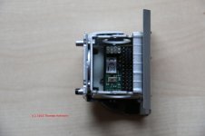
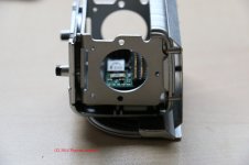
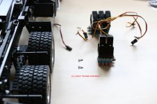
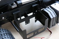
DE: In diesem Sinne: .. das Tüfteln an den Hydraulikleitungen hat mir einiges Kopfzerbrechen bereitet .. dies hat auch dazu geführt, dass ich den Kran noch einmal abbauen musste und die Stützen habe ich sicher 3x an/aufgebaut, bis ich zufrieden war ... doch dazu später mehr. Vor der Verschlauchung wollte ich noch einen Weg finden nicht auch noch 12 Servokabel im Rahmen zu verlegen (9Hydraulik 2 Sperre, 1 Rockinger) ... da bot sich der leere Auspuff an ...

EN prefix: due to intense discussion within various communities between the real builders and the assembly fraction i was pondering, weather its worth continuing this stoy. finally i decided to continue for various reasons: on one side i find the crane very detailed and by reading through this report some other colleagues might be able to assemble one of those themselves and finally i am not forcing the real builder to follow this report :)

EN: it took me some time to get back to you with an update - basically the layout of the hydraulic lines took me a couple of sleepless nights and since i dint get it right at first i had to unmount the crane several times, more at the end of this update. facing the challenge of the hydraulic lines i wanted to ensure that i find a smarter way for the servocabeling (12 in total), the empty exhaust seemd ideal...

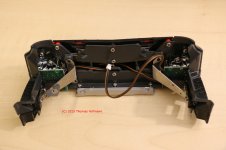
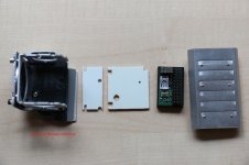
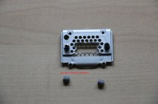
DE: los gehts mit dem Umbau.. Designziel: später leicht an die Servos und das Auswertemodul zu kommen, ohne den LKW zerlegen zu müssen ..
EN: lets start cutting the exhaust.. design objective: easy access to the servos and the brixl auswertemodul, without facing too many disassemlyefforts

DE: 2 Distanzplatten, damit das Auswertemodul einen festen Halt findet
EN: some auxiliary plates to ensure a tight fit
IMG_7741.jpg
IMG_7744.jpg
IMG_7745.jpg

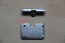
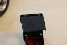
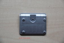
DE: zerschneiden des Deckel
EN: cutting the exhaust top
IMG_7747.jpg
IMG_7749.jpg

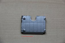
DE: ausschneiden der Kanten
EN: cutting the edges
IMG_7753.jpg
IMG_7751.jpg
IMG_7754.jpg

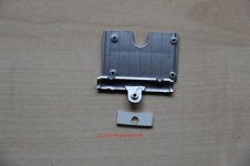
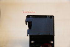
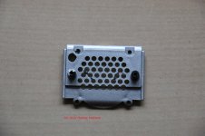
DE: ausschneiden der Rückseite
EN: cutting the rear side
IMG_7756.jpg

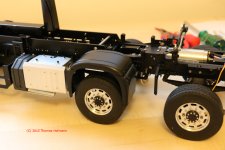
DE: bei der Gelegenheit habe ich auch die ausbrechenden Befestigungen mit Schrumfschlauch gesichert
EN: the screw holders didnt look very durable, so i secured them with a tube as well
IMG_7758.jpg

DE: fertig
EN: done
IMG_7760.jpg
IMG_7762.jpg

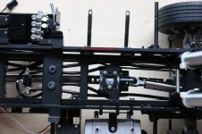
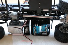
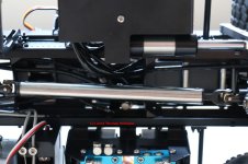
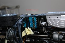
DE: zurück zum Kran und den Stützen und eine kurze Erklärung zur Verschlauchung: insgesamt sind am Fahrgestell 4 Ventilblockgruppen verbaut, die alle mit einer Druck und Tankleitung versehen müssen. beigelegt war ein ungemein bockiger 4mm Schlauch und der 3mm Schlauch war in der Handhabung leider auch nicht sehr widerspenstig.

Druckleitung (P)
Pumpe -> Verteiler (1x 2 Ventile Abroller, 1x 2 Ventile kran "5er" Gruppe).
2er Ventil Block (5er gruppe) -> Verteiler (3 Ventile 5er Block & 2 er Ventile im Kran)

Tankleitungen
ventilblock (Abroller) -> Tank (unten)
Ventilblock 3er ->Ventilblock 2er (im Krankasten) -> Verteiler (Ventilblock Kran) -> Ölkühler -> Tank (Anschluß oben)

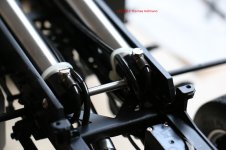
die Stützen haben 2 Stützzylinder und 2 Schubzylinder. die Leitungen werden jeweils über T-Stücke zusammengefasst (insgesamt 4 Stück!!)

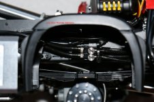
die 2 T-Stücke für die Stützen liegen zwischen den Stützen und dem Hilfsrahmen und gehen dann an das Sperrventil im Kran und von dort an der linken Rahmenseite vorbei in den 5er Block

die 2 T-Stücke zum Ausfahren der Abstützzylinder liegen im Kotflügel der 2. VA - dort ist auch der T-Block für die Tankleitung (über Ölkühler) zu sehen

und nun Bilder ohne viel Worte:

EN: please send me a PN if interested in the cabling instructions :)

IMG_7791.jpg
IMG_7793.jpg
IMG_7794.jpg
IMG_7795.jpg
IMG_7796.jpg

DE: Verschlauchung des 5er (1x2, 1x3) Ventilblocks
EN: wiring the 5 hydraulik valves
IMG_7797.jpg
IMG_7799.jpg
IMG_7800.jpg

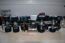
DE: die Unterseite ...
EN: the bottom view
IMG_7801.jpg

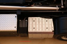
DE: vom Auspuffumbau ist nichts mehr zu erkennen ...
EN: remember the exhaust trick .. cant be recognized anymore
IMG_7807.jpg

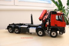
DE: so steht der LKW aktuell am Schreibtisch
EN: current impression from the truck, parking on my desk
IMG_7805.jpg
IMG_7808.jpg

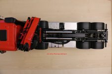
DE: zum Abschluß ein Blick von oben ... die Leitungen auf der linken Seite muss ich noch kürzen / besser verlegen
EN: a view from the top, the lines on the left have to be shortened or secured ...
IMG_7812.jpg
 
Hi Tom, vielen dank diesen Bericht weiterzuführen! :thx

Hat off for figuring out the hydraulic lines! I already had sleepless nights just doing the ones for the roll on/off kipper.
As for that discussion between "assemblers" and "builders" ... kind of pointless really. We all have different skills/interests so I don't see why some people make a problem out of it.

I for one am very happy you continued posting! Always interesting to see how things are made or fit together.

Great update! Thank you!

Stephan
 
Hallo Tom

vielen Dank für den Bericht. Ich bin einer der Fraktion der sich an allem erfreut. Egal ob Bausatzschrauber, Modellkäufer oder Eigenbauer.
Dein neuer LKW wird ja ein richtiges sahnestück. Gratuliere.
 
Hallo Tom,

sieht echt gut aus dein Arocs und mach weiter mit dem detaillierten Bericht hier.

Gruß

Benjamin
 

Servonaut
Zurück
Oben Unten